OPERATING INSTRUCTIONS DIGITAL AUDIO PROCESSOR DP-K1 The various signal processing functions that the DP-K1 can implement are set using the supplied setting software. The manual operation at the DP-K1 is only to recall the programmed setting state (preset memory) and to lock/unlock the knob to prevent accidental wrong operation. For detailed descriptions of each function and its setting procedure, read the software setting instruction manual included in the supplied CD.
TABLE OF CONTENTS 1. SAFETY PRECAUTIONS ................................................................................ 4 2. GENERAL DESCRIPTION .............................................................................. 5 3. FEATURES ........................................................................................................... 5 4. HANDLING PRECAUTIONS ........................................................................... 5 5. NOMENCLATURE AND FUNCTIONS 5.1.
13. LEVEL DIAGRAMS 13.1. Analog Input/Output ........................................................................................ 22 13.2. Digital Input/Output ......................................................................................... 22 14. SPECIFICATIONS 14.1. DP-K1 14.2. D-921F 14.3. D-921E 14.4. D-922F 14.5. D-922E 14.6. D-936R 14.7. D-923AE 14.8. D-937SP 14.9. D-971M 14.10. D-971E 14.11. D-971R 14.12. D-972AE 14.13. D-961SP 14.14. D-981 14.15. D-983 Digital Audio Processor ........
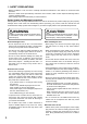
1. SAFETY PRECAUTIONS • Before installation or use, be sure to carefully read all the instructions in this section for correct and safe operation. • Be sure to follow all the precautionary instructions in this section, which contain important warnings and/or cautions regarding safety. • After reading, keep this manual handy for future reference.
2. GENERAL DESCRIPTION The TOA DP-K1 is a 3U rack mountable Digital Audio Processor. It features an Automatic Resonance Control function that automatically generates an optimum filter curve to improve sound clarity after measuring the acoustic characteristics in architectural space. All of this function and other acoustic signal processing functions such as compressor and delay are set by a PC using the supplied setting software.
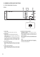
5. NOMENCLATURE AND FUNCTIONS 5.1. DP-K1 Digital Audio Processor [Front] 2 3 4 1 [Inside of the pocket cover] 5 1. Power lamp Lights when the power switch is set to ON. 2. Preset knob Rotating this knob recalls the preset memory. Holding down it for 5 seconds or more locks or unlocks the knob. The numbers and dots marked around the knob are LED indicators. They indicate the currently recalled memory number or communication state between the DP-K1 and the PC. For details, refer to p. 13 and 14. 3.
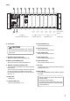
[Rear] 6 7 8 9 10 11 12 13 14 15 16 00-40-9D-26-14-58 9 17 8 7 18 Remote control module slot 6 5 4 3 2 1 Outputs 5–8 Outputs 1–4 Inputs 7&8 Inputs 5&6 Inputs 3&4 Inputs 1&2 Output module slot 6. Cooling Fan CAUTION Do not block the fan exhaust vent. Doing so may cause heat to build up inside the unit and result in fire. Input module slot Slot number Input & output channel Module type 12. Output module slot Slot for output channels 1 – 4. 13.
5.2. Optional Modules Notes • Make sure that the power is switched OFF before attaching or detaching modules. • To avoid failures due to static electricity, do not touch the parts or terminals on the circuit board of both the unit and module. • Ensure that the module is installed and secured with screws in the correct position. • Cover idle slots with the blank panels attached to the unit as shipped by the factory.
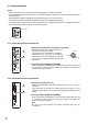
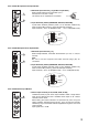
5.2.3. D-922F Microphone/Line Input Module MIC/LINE INPUT MODULE ON NORMAL MIC 1 OFF : PHANTOM LIFT : GND LINE +4dB(LINE) -36dB(MIC) -10dB(LINE) -50dB(MIC) 5 model D-922F OFF : PHANTOM LIFT : GND LINE +4dB(LINE) -36dB(MIC) -10dB(LINE) 1 -50dB(MIC) 2: Hot 1: Ground 6 6. Input Sensitivity Switch [PHANTOM, GND LIFT, MIC/LINE] 4-pole switch. Enables phantom power (+15 V; ON/OFF, enabled only when set to the MIC position), ground lift and input sensitivity.
5.2.6. D-923AE Digital Input Module DIGITAL INPUT MODULE DIGITAL IN 1/2 10 AES/EBU 10. AES/EBU Digital Input Terminal [AES/EBU, 1/2] (XLR-3-31 equivalent) Digital input terminal of AES/EBU format. (Pin 1: Ground; Pin 2: Signal; Pin 3: Signal) Use the XLR-3-12C or its equivalent for 3: Signal connection. Note Use a digital audio cable with characteristic impedance of 110 Ω for connection. 2: Signal 1: Ground model D-923AE 5.2.7.
5.2.9. D-971E Line Output Module LINE OUTPUT MODULE [+4 dB] 14 E 1 C H E C 2 H 14. Monaural Output Terminal [1, 2, 3, 4] Electronically-balanced, removable terminal block. (H: Hot; C: Cold; E: Ground.) Output signal level: +4 dB Note Be sure to use the supplied removable terminal plugs (3P) for connection. E C 3 H E C 4 model D-971E H ACCESSORY I.T.E 78CK 5.2.10. D-971R Line Output Module LINE OUTPUT MODULE [–10 dB] 2(R) 1(L) 4(R) 3(L) 15 15.
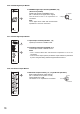
5.2.12. D-961SP Digital Output Module DIGITAL OUTPUT MODULE DIGITAL OUT OPTICAL 1 17 18 COAXIAL OPTICAL 2 COAXIAL 17. Optical Output Terminal [OPTICAL 1, 2] Optical output terminal of S/PDIF format. model D-961SP 18. Coaxial Output Terminal [COAXIAL 1, 2] Coaxial input/output terminal of S/PDIF format. Note Use a coaxial cable with characteristic impedance of 75 Ω for connection. Each pair of the S/PDIF optical output and the coaxial RCA pin jack output delivers output in parallel. 5.2.13.
6. SIGNAL PROCESSING FUNCTIONS The unit features the following signal processing functions. • Automatic resonance control • Compressor function • Noise Gate function • Filter function • Crossover function • Delay function These function settings are performed using the dedicated setting software. For detailed descriptions of the signal processing function, read the software setting instruction manual included in the supplied CD. 7. OPERATIONS 7.1.
8. PC CONNECTIONS 8.1. Connections Connect the PC to the unit's network connection terminal via a switching hub. Use a straight through cable for connection. Notes • To enable communications between the PC and the unit, set the unit's network setting needs to be set on the PC. For communication settings, refer to the software setting instruction manual included in the supplied CD. • The PC can communicate with only one unit at a time.
8.2. Repositioning the Network Connection Terminal WARNING These servicing instructions are for use by qualified personnel only. To avoid electric shock, do not perform any servicing other than that contained in the operating instructions unless you are qualified to do so. Refer all servicing to qualified service personnel. Step 1. Plug out the power cord from the AC wall outlet. WARNING Never do this work with the power cord connected to the outlet, as doing so may cause electric shock. Step 2.
Step 8. Cut the cable tie on the center of the rear-mounted network connection terminal panel. DP-K1 rear 10 8 Cut at 3 places with nippers. Network connection terminal panel 9 Step 9. Remove 2 screws to detach the network connection terminal panel. Note The removed screws are used in Step 13. Step 10. Detach the harness from the backside of the panel, then cut the knockout hole on the center of the panel using nippers. Step 11.
9. RESTORING FACTORY DEFAULT SETTING Step 1. Switch off the unit's power. Input channel indicators Step 2. Switch on the power while holding down the preset knob. All input channel indicators light up. Step 3. After 5 seconds, release the preset knob when the indicators extinguish and all output channel indicators light up. The internal parameter is restored to the factory default setting. Note The network settings are not initialized. Output channel indicators Preset knob 10.
11. CONNECTIONS 11.1. Connection Example Mixer BGM player (Cassette deck, CD player, MD player, etc.
11.2. Removable Terminal Plug Connection Cautions • Be sure to use shielded cables for audio signal lines. • Avoid soldering stranded or shielded cable, as contact resistance may increase when the cable is tightened and the solder is crushed, possibly resulting in an excessive rise in joint temperatures. Cable end treatment Solid or stranded cable Shielded cable 7 mm 7 mm 20 mm Connector connections Slotted screwdriver Step 1.
12.
Line Output Module (D-971M or D-971E) DA SIG LED Gain 1 2 3 4 5 6 7 8 Filter SIG LED ON COMP 4 Delay DA SIG LED ON COMP DA 5 Delay SIG LED Gain DA ON COMP 6 Delay Digital Output Module (D-972AE) SIG LED Gain ON COMP 7 Delay DIT SIG LED Gain Filter DA ON Gain Filter Line Output Module (D-971R) SIG LED COMP Filter 3 Delay Gain Filter DA 2 Delay Gain Filter DA SIG LED ON COMP Filter 1 Delay Gain Filter DA ON COMP ON COMP Delay DIT 8 DIT DIT Digital Outpu
13. LEVEL DIAGRAMS 13.1. Analog Input/Output Microphone/Line Input Module D-921F/921E/922F/922E Stereo Input Module D-936R DSP Line Output Module D-971M/971E/971R Digital dBu (+24 dB) +20 +10 dBu Max. Input (+24) LINE (+4) +20 +10 (+4 dB) (+4) D-971M/971E 0 -10 0 LINE (-10) (-10) D-971R -20 -30 -10 -20 MIC (-36) SIG LED Turns ON (-36 dB) -40 -50 MIC (-50) 13.2. Digital Input/Output Digital Input Module D-923AE/937SP DSP Max.
14. SPECIFICATIONS 14.1.
14.2. D-921F Microphone/Line Input Module (Optional) Input A/D Converter Sampling Frequency Frequency Response Dynamic Range Total Harmonic Distortion Finish Dimensions Weight 2 channels, Mic/Line changeable Mic: –50/–36 dB*, 4.
14.5. D-922E Microphone/Line Input Module (Optional) Input A/D Converter Sampling Frequency Frequency Response Dynamic Range Total Harmonic Distortion Finish Dimensions Weight 2 channels, –50/–36/–10/+4 dB* (Selectable with the DIP switch), 4.
14.9. D-971M Line Output Module (Optional) Output D/A Converter Sampling Frequency Frequency Response Dynamic Range Total Harmonic Distortion Finish Dimensions Weight 4 channels, +4 dB*, adaptable load of over 600 Ω, electronically-balanced, equivalent to XLR-3-32 type 24 bits 48 kHz 20 Hz – 20 kHz, ±1 dB Over 100 dB (IHF-A weighted) Under 0.05% Panel: Pre-coated steel plate, black (30% glossy) 35 (w) x 119.5 (h) x 178.4 (d) mm 165 g 14.10.
14.13. D-961SP Digital Output Module (Optional) Output Applicable Format Sampling Frequency Finish Dimensions Weight Stereo 2 channels (with splitter, each pair of optical output and coaxial output in parallel), 0.5 V (p-p), 75 Ω, Coaxial RCA jack x 2 Square optical connector x 2 S/PDIF (2 channel multiplexed) 48 kHz Panel: Pre-coated steel plate, black (30% glossy) 35 (w) x 119.5 (h) x 178.4 (d) mm 130 g 14.14.
14.15. D-983 Remote Control Module (Optional) Contact Input Preset Memory Selection Control Volume Control Mute Contact Output Finish Dimensions Weight COM + Terminals 1 – 24: Open voltage 5 V DC, short-circuit current 5 mA, RJ45 connector x 4 Any preset memory can be recalled. Control method: No-voltage make of over 100 ms or no-voltage make single pulse of over 100 ms Any input/output channel volume can be turned UP or DOWN.