
Instruction Manual

5. INSTALLATION
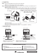
Step 1. Installtheelectricalboxintothewall.
Step 2. Make a hole in the wall to mount the unit, then pull out the cables from the wall.
Step 3. Connect the cables to the unit’s terminal block.
Note: Fordetails,see“Connection”onthenextpage.
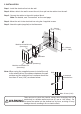
Step 4. Mounttheunitintheelectricalboxusingthe2suppliedscrews.
Step 5. Attachtheplate(supplied)totheAttenuator.
Note: Whenusingthesuppliedscrewstoinstalltheunit
totheelectricalbox,thedistancebetweenthewall
surfaceandtheelectricalbox’ssurfaceshouldbe
lessthan27mm(1.06")asshownbelow.
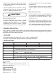
Take care not to pinch the lead-in cables when mounting the unit
particularlyinashallowwall-mountbox(37mmor1.46" deep). Do
notpressthecablesintotheshallowboxbyforce,asdoingsomay
damagetheunit,resultinginreorelectricshock.
WARNING
95 − 103 mm
(3.74" − 4.06")
51 − 59 mm
(2.01" − 2.32")
Machine screw M4 x 35
(Accessory)
Machine screw M3.5 x 5
(Accessory)
Plate (Accessory)
Attenuator
Wall
Cable
83.5 mm
(3.29")
2
1
3
5
4
Max. 27 mm (1.06")
Wall
A recessed
electrical box