OPERATING INSTRUCTIONS SPEAKER SYSTEM H-1 Please follow the instructions in this manual to obtain the optimum results from this unit. We also recommend that you keep this manual handy for future reference. TABLE OF CONTENTS 1. SAFETY PRECAUTIONS 2 2. GENERAL DESCRIPTION 3 3. FEATURES 3 4. HANDLING PRECAUTIONS 3 5. NOMENCLATURE 4 6. INSTALLATION 6.1. 6.2. 6.3. 6.4.
1. SAFETY PRECAUTIONS • Be sure to read the instructions in this section carefully before use. • Make sure to observe the instructions in this manual as the conventions of safety symbols and messages regarded as very important precautions are included. • We also recommend you keep this instruction manual handy for future reference.
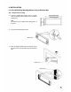
2. GENERAL DESCRIPTION TOA's H-1 is a cylinder-shaped, small flush-mount 2-way speaker featuring high sound quality. 3. FEATURES • The H-1 Speaker System features, flush-mount speaker design with a rotatable cylinder-type enclosure. The speaker's smooth curved surface allows it to blend in with the interiors of most modern buildings. • The speaker's small ( 8 x 5 cm) woofer features a magnetic circuit (employing a neodymium magnet) that ensures powerful sound reproduction.
5.
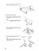
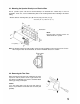
6. INSTALLATION 6.1. Direct Wall/Ceiling Mounting Without Using an Electrical Box Step 1. Adapter Panel mounting 1-1. Using the supplied hole pattern sheet as a guide, make an opening of the specified size in the wall or ceiling panel. Note The thickness of the suitable wall or ceiling panel is 9 to 30 mm. 1-2. Loosen the two board clamp screws. Board clamp 1-3. Place the Adapter Panel inside the opening, and set the panel to the desired position using the positioning tabs.
1-4. Clamp the wall or ceiling panel using the two board clamps, and secure with the clamp screws. Step 2. Wiring and impedance changes 2-1. Pull the cables out of the mounting hole in the wall or ceiling, then strip the insulation back about 5mm from the cable ends. Note 2 Usable cable: Solid cable or stranded cable (0.2 mm 2 - 2.5 mm ) (Corresponding to AWG No. 24-14) About 5 mm 2-2. Remove the detachable input connector from the speaker, then loosen the connector screws with a small slot screwdriver.
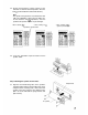
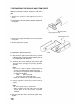
2-4. Attach two impedance selector sockets to the connector to select the desired impedance. Preset to 830 (12 W for 100 V line and 6 W for 70 V line). Note The speaker is designed to be used for both 70 V and 100 V line applications. When using the 100 V line, do not select the "420 " impedance, since the speaker itself or power amplifier may be damaged. • When selecting 4 • When selecting 16 Impedance selector socket • When selecting 830 (preset by the factory) 2-5.
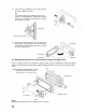
3-2. Loosen the angle adjustment screws. After adjusting the angle, retighten the screws. Tip The mounting angle can be adjusted for up to ± 45 °. Since the mounting bracket is marked with mounting angles at 15 ° intervals, use this marking as a guide when adjusting the angle. Stud screw Angle adjustment screw 3-3. Align the two securing clips on the Trim Piece with the speaker's two stud screws, then push the Trim Piece onto the speaker until the Trim Piece is snug to the wall or ceiling surface.
6.3. Mounting the Speaker Directly to an Electrical Box The H1 speaker system can also be mounted directly to an electrical box*. Follow Steps 2 and 3 for instructions. In this case, use the outward-facing holes in the mounting bracket when mounting to the wall or ceiling. * Distance between mounting holes (A) x (B): 254 mm (10") x 66.7 mm (2 5/8") or 255.6 mm (10 1/10") x 55.6 mm (2 3/16") Electrical box Memo Electrical box mounting screws are attached to the H-1 speaker.
7. REPAINTING THE GRILLE AND TRIM PIECE Follow the procedures below to change the color of the grille. 1. Remove the speaker's angle adjustment screw (1 piece). 2. Detach either of the two mounting brackets attached to the speaker. Mounting bracket Angle adjustment screw Grille mounting screw 3. Remove the two grille mounting screws from the back of the speaker. 4. Slide the grille off the speaker. 5. Paint both the grille and Trim Piece. 5-1.
7. Attach the grille to the speaker with its two mounting screws. 8. Reattach the mounting bracket to the speaker with the angle adjustment screw. 8. PROTECTION CIRCUITRY INFORMATION • The speaker has built-in overload protection circuitry. If there is an extremely high level input signal to the speaker, the overload protection circuitry is activated and cuts off the signal input to the speaker component.
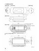
10. SPECIFICATIONS Enclosure Type Power Handling Rated Input Rated Impedance Output Sound Pressure Level Frequency Response Crossover Frequency Speaker Element Input Terminal Usable Cable Material and Finish Dimensions Weight Sealed type 90 W (continuous program input, 4 loaded) 30 W (continuous pink noise input, 4 loaded)*1 12 W (16 or high impedance) 4 , 16 70V line: 420 (12 W), 830 (6 W), 1.7k (3 W), 3.3k (1.5 W) 100 V line: 830 (12 W), 1.7 k (6 W), 3.