OPERATING INSTRUCTIONS SPEAKER SYSTEMS F-2000B F-2000BT F-2000BTWP F-2000W F-2000WT F-2000WTWP Thank you for purchasing TOA's Speaker System. Please carefully follow the instructions in this manual to ensure long, trouble-free use of your equipment.
TABLE OF CONTENTS 1. SAFETY PRECAUTIONS ................................................................................. 3 2. GENERAL DESCRIPTION .............................................................................. 4 3. FEATURES ........................................................................................................... 4 4. DIMENSIONAL DIAGRAM .............................................................................. 4 5.
1. SAFETY PRECAUTIONS • Before installation or use, be sure to carefully read all the instructions in this section for correct and safe operation. • Be sure to follow all the precautionary instructions in this section, which contain important warnings and/or cautions regarding safety. • After reading, keep this manual handy for future reference.
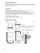
2. GENERAL DESCRIPTION TOA's F-2000 Series Speakers are compact two-way speaker systems designed for high efficiency, wide range, and high power input handling capability. These speaker systems can be installed in a manner ideal for the location and intended application. 3. FEATURES • • • • 100º horizontal x 100º vertical wide directivity high-frequency horn. Coverage angle can be changed to 80º horizontal x 80º vertical by attaching the supplied horn adapter.
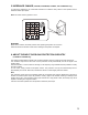
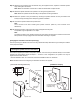
. IMPEDANCE CHANGE (F-2000BT, F-2000BTWP, F-2000WT, and F-2000WTWP only) To change the impedance, use a standard screwdriver to rotate the rotary switch on the speaker's rear to select the desired input power. Note: The switch is factory-preset to 170 . Important Never set this switch to the "83 " position when operating the speaker on 100 V line. Failure to follow this instruction could result in damage to the speaker or amplifier. 6.
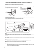
7. NOTES ON OUTDOOR INSTALLATION (F-2000BTWP and F-2000WTWP only) • Be sure to mount the speaker in a vertical (portrait-style) orientation. • Adjust the speaker's tilt angle within the shaded range shown below: [Wall and pole: 0º horizontal to 45º downward] Note Mount the speaker so that its rear-mounted terminal cover is positioned on the upper side. [Under eaves: 15º downward to 45º downward] Note The speaker faces 15° downward when mounting to a horizontal surface.
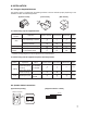
8. INSTALLATION 8.1. Using the Supplied Brackets The speaker system is supplied with the following brackets. Use these brackets properly depending on the installation location and intended application. [Speaker bracket] [Joint bracket] [Wall bracket] 30º 8.1.1. When using only the supplied brackets Installation Location Wall Ceiling Speaker Stand (Option) Application Speaker bracket Joint bracket Wall bracket Page When horizontal and vertical angle adjustability is desired. P.
.3. Wall Mounting When adjusting horizontal and vertical angles: Use the supplied wall bracket, joint bracket, and speaker bracket to permit adjustment of the horizontal and vertical* speaker coverage angles. * Vertical installation. Horizontal installation. Horizontal: Max. 70º, Vertical: Max. 45º downward Horizontal: Max. 45º, Vertical: Max.
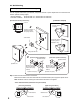
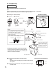
Step 2. Attach the joint bracket to the wall bracket using the supplied screws, adjust the horizontal speaker angle, then tighten the screws. Note: Match the orientation of the arrows on both the wall bracket and joint bracket. Step 3. Attach the speaker bracket to the speaker's rear using the supplied screws. Note: Attach the speaker bracket according to the speaker mounting orientation. Step 4.
8.4. Ceiling Mounting Vertical orientation Use the supplied joint bracket and speaker bracket. Note Speaker coverage angles can only be adjusted in the vertical direction (Max. 45º downward). Adjust the speaker's tilt angle within the shaded range shown below: [Installation example] [Speaker angle vs.
Step 3. Mount the speaker to the joint bracket by inserting the speaker bracket into the joint bracket and loosely securing the fixing bolt for temporary speaker installation. Step 4. Connect the speaker cable to the input terminal. Note Use a terminal cover when installing the speaker outdoors. (Refer to p. 6 for terminal cover attachment.) Step 5. Adjust the speaker's vertical mounting angle and tighten the fixing bolt. The speaker angle is adjustable in 7.5º steps.
8.5. Speaker Stand Mounting The speaker can be mounted on the optional ST-16A Speaker Stand using the supplied joint bracket and speaker bracket. [Installation example] Speaker unit As hole seals are adhered over the holes, remove them using a pointed tool before attaching the bracket. Machine screw M5 x 20 (with plain washer and spring washer) 2 Butterfly nut (supplied with the ST-16A) Washer (supplied with the ST-16A) Max.
8.6. Pole Mounting (F-2000BTWP and F-2000WTWP only) To mount the speaker on a pole with diameter of 9 – 34 cm, use the supplied wall bracket, joint bracket, and speaker bracket in combination with the optional SP-131 Pole Mount Bracket and YS-60B Pole Band. Speaker coverage angles can be adjusted in the horizontal and vertical direction*. [Installation example] * Horizontal: Max. 90º, Vertical: Max. 45º downward Note Although the SP-131 comes in 2 sets of brackets, use one set only.
Step 1. Attach the wall bracket to the SP-131 Pole Mount Bracket. Match the orientation of the arrow label with the horizontal direction (left or right) the speaker faces. Use the bolts supplied with the SP-131. • Arrow label orientation (Viewed from top of brackets) [Right-facing orientation] [Left-facing orientation] Pole Pole SP-131 Wall bracket SP-131 Wall bracket Arrow label Arrow label Joint bracket Joint bracket Step 2. Attach the SP-131 to a pole using the YS-60B. Step 3.
9. REDUCING THE SPEAKER COVERAGE ANGLE The speaker's coverage angle can be reduced to 80º horizontal x 80º vertical from its normal range of 110º x 110º by attaching the supplied horn adapter to the speaker's horn section. [Without horn adapter] 110º horizontal [With horn adapter] 80º horizontal 80° vertical 100° vertical [Attaching the horn adapter] Horn adapter Note Take care not to touch the speaker diaphragm during attachment.
10. REPAINTING THE SPEAKER Follow the procedure below when repainting the speaker grill and cabinet. Note Take care not to touch the speaker diaphragm during work. Step 1. Peel off the logo carefully, then remove the screw underneath to detach the mesh speaker grill. [Detaching the mesh grill] Mesh speaker grill Countersunk head tapping screw 4 x 12 Baffle (Masking area) Logo Note Because the logo is affixed using double-faced tape, peel it off carefully. Step 2.
11. SPECIFICATIONS 11.1. F-2000B and F-2000W Model No.
11.2. F-2000BT and F-2000WT Model No. Enclosure Type Power Handling Capacity Rated Impedance Output Sound Pressure Level Frequency Response Crossover Frequency Directivity Angle Speakers Input Terminals Enclosure Mesh Speaker Grill Speaker Bracket Joint Bracket, Wall Bracket Dimensions Weight Accessories Optional Products F-2000BT F-2000WT Bass-reflex type 60 W 170 (60 W), 330 (30 W), 670 (15 W), 3.
11.3. F-2000BTWP and F-2000WTWP Model No. Enclosure Type Power Handling Capacity Rated Impedance Output Sound Pressure Level Frequency Response Crossover Frequency Directivity Angle Speakers Input Terminals Water Resistance Operating Temperature Enclosure Mesh Speaker Grill Speaker Bracket Joint Bracket, Wall Bracket Dimensions Weight Accessories Optional Products F-2000BTWP F-2000WTWP Bass-reflex type 60 W 170 (60 W), 330 (30 W), 670 (15 W), 3.