INSTRUCTION MANUAL COLOR CAMERA C-CV14-2 NTSC C-CV14-2 PAL Thank you for purchasing TOA’s Color Camera. Please carefully follow the instructions in this manual in order to ensure long, trouble-free use of your color camera.
TABLE OF CONTENTS 1. SAFETY PRECAUTIONS ................................................................................ 3 2. GENERAL DESCRIPTION ............................................................................. 4 3. HANDLING PRECAUTIONS .......................................................................... 4 4. NOMENCLATURE ............................................................................................. 5 5. INSTALLATION .........................................................
1. SAFETY PRECAUTIONS • Before installation or use, be sure to carefully read all the instructions in this section in order to ensure long, trouble-free operation. • Be sure to follow all the precautionary instructions in this section, which contain important warnings regarding safety. • After reading, keep this manual handy for future reference.
NTSC complies with Part 15 of the FCC Rules. Note This equipment has been tested and found to comply with the limits for a Class B digital device, pursuant to Part 15 of the FCC Rules. These limits are designed to provide reasonable protection against harmful interference in a residential installation. This equipment generates, uses and can radiate radio frequency energy and, if not installed and used in accordance with the instructions, may cause harmful interference to radio communications.
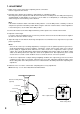
4. NOMENCLATURE 5 1 2 4 3 6 24V 12V + - IRIS OFF H L ON FOUCUS ADJ BLC SHUTTER VIDEO OUT 7 10 8 9 11 (1) Vari-focal lens (7) Iris control (2) Focus ring (8) Video output terminal (BNC) (3) Zoom ring (9) Mode setting switch (4) Camera mount (10) Lens cover (5) Camera mount fixing screw (11) Camera mount fixing hole (6) Power input terminal (24 V AC or 12 V DC) Note Fixing holes (11) are provided in both the top and bottom panels.
5. INSTALLATION [Ceiling mounting example] [Wall mounting example] Ceiling panel Camera mounting bracket (optional) Wall Lock lever Pedestal Camera mount Camera mounting bracket (optional) Wall WARNING Install the unit only in a location that can structurally support the weight of the unit and the mounting bracket. Doing otherwise may result in the unit falling down and causing personal injury. Camera mounting bracket (optional) 1. Mount the optional camera mounting bracket to a ceiling or wall.
5.1. Lens Cover Attachment and Detachment To detach, lightly press on both the top and bottom of the lens cover and pull it forward. To attach, align the clips inside the lens cover with the corresponding camera tabs, then press on the cover. Press on this section (top and bottom, 2 places) and pull forward to detach the lens cover. Inside of the lens cover Lens cover Clips Tabs (left and right) fit into cover clips, which snap into holes when correctly attached. 6.
7. ADJUSTMENT 1. Switch on the camera power after completing camera connections. Power is supplied to the camera. 2. Normally,set the Shutter Speed switch to "1/60"(NTSC) or "1/50"(PAL) position. Flickering of the picture may interfere with the view under fluorescent lamp in the area with power frequency of 50 Hz(NTSC) or 1/60 Hz(PAL). In such cases, set the switch to "1/100"(NTSC) or "1/120"(PAL) position, and the image free from flickering can be obtained.
8. ABOUT THE MODE SETTING SWITCH Set the Mode Setting switch for the best possible picture reproduction depending on installation conditions. Mode Setting Switch (Factory-preset setting) 24V 12V + IRIS L OFF ON OFF H Adjustment switch Backlight Compensation switch Shutter Speed switch ON FOUCUS ADJ BLC SHUTTER VIDEO OUT (NTSC) 1/60 (PAL) 1/50 1/100 1/120 8.1. Adjustment Switch Set this switch when adjusting the lens focus.(Provides the same effect as when using the ND filter.
9. IF YOU THINK THERE IS A FAILURE: (TROUBLESHOOTING) Possible Cause Symptom Camera images are • The monitor’s power switch is not not displayed on the set to ON. • Cables are not correctly connected. monitor. • The BNC plug is not correctly soldered. • Power is not supplied to the camera. Pictures are not clear. • The lens is not properly focused. • The lens is dirty. • Monitor image black level is not correctly adjusted. The color of the picture • The Adjustment switch is set to the ON position.
10. SPECIFICATIONS Model No. Power Source Power Consumption Image Device Number of Effective Pixels Scanning System Scanning Frequency Video Output Synchronizing System Resolution S/N Ratio Minimum Illumination White Balance Mode Focal Length Maximum Aperture Ratio Iris Angle of View Control Switch Other Functions Shutter Speed Operating Temperature Operating Humidity Finish Dimensions Weight C-CV14-2 (NTSC) 24 V AC, 50/60 Hz, or 12 V DC 2W 1/4” IT-CCD 768 (H) x 494 (V), 380,000 pixels 2:1 interlace 15.
Printed in Vietnam 133-12-869-5D