
Install Instructions

6
IMPORTANT
The capacitor for the RT-Series fan should remain within the junction box of the flexible whip. Do not install within fan motor com-
partment.
Failure to wire cooling fan as directed voids warranty.
Installer must supply overload and disconnect protection as dictated by local and national codes. Do not use a fused disconnect.
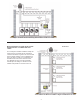
INSTALLING RT-SERIES FAN ELECTRICAL WHIP
The RT series fan is shipped with an Electrical Whip Assembly which is not connected to the fan. Follow these instructions to con-
nect and wire the whip to the fan. Pull the wires out of the fan through the gasketed hole provided on the fan cover of the RT unit
and wire nut the fan leads to the corresponding colored wires on the free end of the whip.
Remove the (2) 8-32 nuts holding the gasket on the electrical access cover of the RT-Series fan. Carefully stuff the wire nutted
connections back into the fan and secure the cover plate and gasket to the fan housing using the nuts removed in the above step.
Firmly tighten the (2) 8-32 nuts until the gasket compresses.
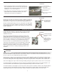
RT-SERIES FAN CONNECTIONS TO COP CONTROL
Secure the junction box on the opposite end of COP whip to the power supply conduit. Wire nut the 5 leads from the COP (Red,
White/Red, Ground, Black and White) to the corresponding colors of the RT-Series Whip. Stuff Wires into 4 x 4 box on whip. Place
provided gasket on 4 x 4 weather tight box opening. Install the 4 x 4 box cover to the j-box and firmly tighten with provided screws
until the gasket compresses.
CDB-SERIES FAN CONNECTIONS TO COP CONTROL
Install metal conduit containing 5 leads, (Red, White/Red, Ground, Black and White) between the COP2DB and CDB8 Fan. Fasten
to CDB8 Leads with wire nuts and connect wires to COP2DB terminal strip as depicted in wiring diagram.
IMPORTANT: Installer must supply overload and disconnect protection. COP Control power may be switched through a building
management system, pressure switch or other 115 VAC switch
Connect 115 VAC supply voltage to L1, N and the ground terminal of the COP right side power terminal strip. Connect Cooling
Fan BLK and WHT terminals of COP right side power terminal strip to the Black and White cooling fan leads of the Exhaust Fan.
Connect Red, WHT/RED stripe & Ground of COP right side power terminal strip the corresponding colored wires of the Exhaust
Fan.
TRANSDUCER CONNECTIONS
Connect the V+, COM and 1-10 V terminal of the COP terminal strip to the corresponding terminals within the j-box of the
Transducer.
ACTIVATION CONNECTIONS
Use any type of dry contact switch to close RUN position C1 to C2 to activate COP. Alternatively, jumper position C1 to C2 for
constant operation.
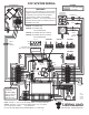
REMOVING POWER FROM & RESETTING VFD DRIVE
A fault can be reset on the VFD Drive if the call to C1 & C2 RUN terminals is removed and/or the Power Switch to the VFD Board
in lower right of COP box is turned off for a minimum of 1 minute so capacitors can fully discharge. IMPORTANT: Cycling the VFD
Power Swich off/on without at least a minute delay may result in damage to the VFD.
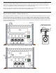
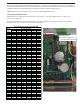
DIAGRAM F
WARNING: This power switch is for the VFD only. 115 VAC to BLK & WHT
from COP to Exhauster cooling fan, 115 VAC to COP VFD cooling fan and
24 VAC power supply to Transducer will still be live! Disconnect main
braker that supplies 115 VAC to L1 & N on COP Control if it is necessary
to disconnect all power in the COP control, (See Diagram F).