
Install Instructions
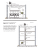

PRESSURE SENSING TUBE INSTALLATION
1. Follow sensing tube location recommendations on pages 3-4.
Use a sharp drill bit to reduce burr, drill a 1/4" hole for pressure
sensing tube. Screw sensing tube bracket to duct/chase with
sampling hole centered, (See Diagram C).
2. Insert stainless steel sensing tube through 1/4" hole enough to
just penetrate interior of duct/chase and lock in place with
compression ferrule and nut, (See Diagram C).
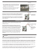
PRESSURE TRANSDUCER MOUNTING AND TUBING CONECTION
Using the key hole slots on the back of the Pressure Transducer junction box
as a template, mark (2) holes on the mounting surface, drill 1/4” pilot holes for
wall anchors if necessary, and secure junction box using provided screws.
Using the included flexible tubing connect the sensing tube to the barbed port
on the exterior of the Pressure Transducer junction box. Excessive additional
lengths of tubing will delay the response of the VFD which can lead to control
lag, (See Diagram D).
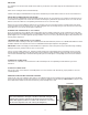
SYSTEM TEST PROCEDURE
If using COP2 with RT-Series in conjunction with oil or gas fired heating
equipment, follow the interlock test procedure outlined within the CIC1
installation instructions.
After wiring is complete with supply power switched on and the COP
activation RUN terminals C1 & C2 closed with a switch or jumper, the
Exhaust Fan will run. The fan should operate and maintain the factory set
point of -0.10” W.C. Disconnect the sensing tube from the barbed fitting
on the Transducer electrical box. The fan should ramp to full speed.
Reconnect the tube. The fan should slow down to the original speed.
This change in fan performance can be demonstrated by viewing a draft
gauge that is teed into the tubing from the Pressure Transducer, (See
Diagram E). Draft gauge should be connected as close as possible to
COP Transducer to achieve a reading on draft gauge similar to COP
Transducer.
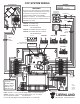
WIRING
The COP must be wired by a qualified installer (an individual properly licensed and/or trained) in accordance with these instruc-
tions and in accordance with all local codes or in their absence, with the current editions of NFPA 70, National Electrical Code in
the U.S. or CSA C22.1-12 Canadian Electrical Code in Canada.
All wiring from the COP to the Dryer Exhaust Fan junction box must be appropriate Class 1 wiring as follows: installed in rigid
metal conduit, intermediate metal conduit, rigid non-metallic conduit, electrical metallic tubing, Type MI Cable, Type MC Cable, or
be otherwise suitably protected from physical damage. Transducer wiring should be in metal conduit or utilize shielded cable.
COP Control supply power may be switched through a building management system, pressure switch or other 115 VAC switch.
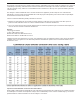
The maximum distance VFD output power from the COP to Dryer Exhaust Fan Motor is 100 feet. Exceeding this distance can
result in undesirable COP and Exhaust Fan operation and possible damage to both the fan and the control.
The maximum distance control signal wire can be ran from the COP to Pressure Transducer is 250 feet. Exceeding this distance
can result in lower than desired signal strength. Transducer wiring should be in metal conduit or utilize shielded cable. Non-
shielded signal wiring can be influenced by outside conditions resulting in undesirable operation of the COP control.
5
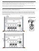
DIAGRAM C
1/4” STAINLESS STEEL
SENSING TUBE BEND MUST
FACE UPWARD
COMPRESSION FERRULE
COMPRESSION NUT
SAMPLING PORT CENTERED
OVER 1/4” HOLE
DIAGRAM D
TO PRESSURE SENS-
ING TUBE IN VENT
COMMON MANIFOLD
DIAGRAM E
TO PRESSURE SENSING
TUBE IN VENT COMMON
MANIFOLD
TO DRAFT GAUGE
CONNECT HERE WHEN
USED FOR SETUP OR
IF PERMANENTLY
INSTALLED.
WARNING
!