
Install Instructions

3
COP INSTALLATION
The COP is intended for indoor installation only. Do not mount the COP on a heat source or in an environment that exceeds
104
o
F (40
o
C). Examples of improper mounting surfaces include vent pipe, top of heater casing or any place where radiant or
convective heat would cause the junction box temperature to exceed temperature limits.
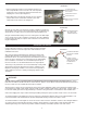
Using the key hole slots on the back of the COP junction box as a template, mark (4) holes on the mounting surface, drill 1/4” pilot
holes for wall anchors if necessary, and secure junction box using provided screws.
PRESS
URE SENSING TUBE LOCATION
PRESSURE SENSING TUBE LOCATION
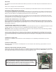
MULTIPLE DRYERS JOINED IN A COMMON HORIZONTAL DUCT
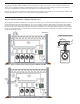
The sensing tube should be installed in the vent cap of a tee or at the rear of a common exhaust manifold, in back of the vent con-
nector that is farthest from the Dryer Exhaust Fan. The tee is necessary so that only static pressure is measured, (See Diagram
A). If the pressure sensing tube is installed in the side of a duct it will also measure velocity pressure, giving an incorrect signal
back to the COP Control. If mounting on the side of the duct is unavoidable, the sensing tube should be flush to the interior wall of
the duct. Avoid sampling near or in elbows. Duct connections should be sealed to prevent leakage or entrainment. Installer must
provide access for lint clean out.
BEHIND THE DRYER FURTHEST FROM INDUCER
BE LOCATED TWICE THE MANIFOLD DIAMETER
IF POSSIBLE, THE SENSING TUBE SHOULD
D
2D
DRYER FURTHEST
FROM THE INDUCER
MINIMUM
XCOP1
SENSING
TUBING TO
DIAGRAM A
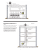
Dryers Common Vented Vertically with CDB8 & COP2DB
Dryers Common Vented Through Side Wall with CDB8 & COP2DB
DRYER FURTHEST
FROM EXHAUST FAN
IF POSSIBLE, THE SENSING TUBE SHOULD
BE LOCATED ONE MAINIFOLD PIPE DIAMETER
BEHIND THE DRYER FURTHEST FROM INDUCER
SENSING
TUBING TO
TRANSDUCER
1 D
MINIMUM