
Manual

4
UC1 INSTALLATION
Do not mount the UC1 junction box on a heat source that exceeds 140
o
F (60
o
C). Examples of improper mounting surfaces
include vent pipe, top of heater casing or any place where radiant or convective heat would cause the junction box temperature to
exceed 140
o
F. The UC1 is intended for indoor installation only.
Using the key hole slots on the back of the UC1 junction box as a template, mark 4 holes on the mounting surface, drill pilot holes
if necessary, and secure junction box using provided screws.
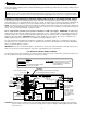
The UC1 has a 2 foot whip that contains a ground lead and the leads to power the Venter motor and connect to the Fan Prover. If
it is desirable to mount the UC1 more than 2 feet from the Fan Proving Switch an additional electrical junction box and appropriate
length of conduit will be necessary. Any added wire should be 14 gage and a pig tail should be added to each ground wire con-
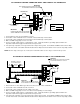
nection so that each electrical junction box is grounded. See diagram below for a typical UC1, Fan Prover and Venter installation.
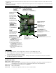
TYPICAL UC1, FAN PROVER AND VENTER INSTALLATION
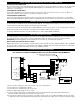
ELECTRICAL WIRING
ELECTRICAL SPECIFICATIONS
FAN PROVER
VENTER
UC1
ALUMINUM SENSING TUBE, 4 FT. MAXIMUM LENGTH
2 FT. MAXIMUM LENGTH UNLESS ADDITIONAL
CONDUIT AND J-BOX ARE ADDED
INSTALLER-SUPPLIED CONDUIT
AND 3 WIRE, MINIMUM 14 GAGE
INSTALLER-SUPPLIED
115 VAC CONNECTION
BURNER INTERLOCK
CONNECTION
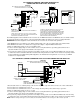
INSTALLER-SUPPLIED
POWER
REQUIREMENTS
EXTERNAL
POWER SWITCHING
CAPACITY
J1 / J2
JUMPER
SAFETY
CIRCUIT
ADD VENTER MOTOR
LOAD PLUS 1/2 AMP
FOR UC1 LOAD
EXTERNAL
CALL TRIGGER
METHODS
J1 / J2
P1 / P2
L / N
3 TO 4
T-BLOCK
T-BLOCK
(RELAY K1)
XL / XN
UC1 CONTROL
M & MTR
(RELAY K2)
T-BLOCK
A / B
24V
1 / 2
115V
1 / 2
OR
OR
USED TO JUMP CALL HOT (24 VAC) OR CALL LINE (115 VAC) FROM TERMINAL 1 TO TERMINAL 3.
CONNECTED TO FAN PROVER.
1 mA @ 5 VDC. DO NOT SUPPLY POWER HERE.
REMOVE J1-J2 JUMPER IF A DIFFERENT VOLTAGE SOURCE IS PROVIDED TO TERMINAL 3.
120 VAC ±10 %, 50/60 Hz
MOTOR - 1 H.P. MAX. @ 120 VAC, 50/60 Hz
USER-PROVIDED 24 VAC AT TERMINALS 1 & 2. 1 = CALL HOT, 2 = COMMON. CONTROL
REQUIRES 5 mA @ 24 VAC TO TRIGGER. MOVE RED VOLTAGE JUMPER TO "24V" LOCATION.
3 mA @ 5 VDC. MOVE RED VOLTAGE JUMPER TO "DRY" LOCATION. DO NOT SUPPLY POWER.
USER-PROVIDED CONTACT CLOSURE FROM A TO B. SIZE CONTACT CLOSURE TO HANDLE
GENERAL PURPOSE - 15A @ 120 VAC, 50/60 Hz
DURING OPERATION THE CONTROL USES 50 mA MAX @ 120 VAC
MOTOR - 1 H.P. MAX. @ 120 VAC, 50/60 Hz
150 mA MAX @ 120 VAC, 50/60 Hz
CAN ONLY BE CONNECTED TO TJERNLUND-SPECIFIED AUXILIARY DEVICE
CIRCUIT PROTECTION PROVIDED BY INSTALLER
GENERAL PURPOSE - 15A @ 120 VAC, 50/60 Hz
RESISTIVE - 10A @ 28 VDC PILOT DUTY - 470 VA
USER-PROVIDED 115 VAC AT TERMINALS 1 & 2. 1 = CALL LINE, 2 = NEUTRAL. CONTROL
REQUIRES 1 mA @ 115 VAC TO TRIGGER. MOVE RED VOLTAGE JUMPER TO "115V" LOCATION.
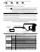
P1 & P2 FAN PROVER SAFETY CIRCUIT “OPEN” UPON APPLIANCE CALL
Prover Status
Check Activated
The Prover Status Check is activated from the factory. When activated the UC1 Universal Control
checks across P1 & P2 safety circuit (Fan Prover) to verify that the Fan Prover switch is “Open”
upon a call for heat and not stuck “Closed”. IMPORTANT: This must always be in the down
“Activated” position when side wall venting. When using the PS1505 Fan Prover in conjunc-
tion with a draft inducer on a vertical termination stack, “natural draft” may be sufficient to keep
Prover contacts closed prior to a call for heat by an interlocked appliance. This is the only condi-
tion where this safety feature should be deactivated. Push up or “ON” to deactivate.
9
ON
PRE-PURGE SETTINGS
(SEE “PRE-PURGE” ON PAGE 3 PRIOR TO SETTING PRE-PURGE)
1 2 1 2 1 2 1 2
0 Seconds 5 Seconds 20 Seconds 35 Seconds
POST-PURGE SETTINGS