
Manual


CONTROLLER
T M
M
LO
B
ACTUATOR
T Hi
Hot
Cold
ACTUATOR
CONTROLLER
Lo
M
B
Hi
T
PNEU-DD-IOM-2.0 8-9-02
Adjusting Minimum and Maximum Air Flow for Units with Hot Inlet Sensor and Cold Discharge
Sensor
A. Direct Acting Thermostat Air
Flow Adjustment
1. Hot inlet controller. Be sure the hot
inlet damper assumes a fully closed
position during cooling conditions.
Apply 15-25 PSI pressure to the
thermostat connection of the hot
inlet controller. If the hot inlet
damper does not fully close, adjust
LO air flow know until the damper
closes. Allow several seconds for
the controls to react to system
pressure and stabilize.
To adjust hot deck maximum CFM:
a. Apply zero PSI to the
thermostat connection on the
hot deck controller. Place a
manometer gauge across the
balancing tees at the hot deck
inlet.
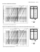
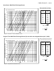
b. If the manometer gauge
reading matches the required
differential pressure from the
calibration curve (Page 6 and
7), no adjustment is
necessary.
c. If adjustment is necessary, use
the adjusting tool stored in the
face of the controller (Titus II
only) or a standard flat-blade
screwdriver.
d. Rotate the maximum HI knob
slowly. A delay in response
time has been deliberately built
into the controls to avoid
hunting. Allow several seconds
from controls to react and the
system to stabilize. Rotate the
know until the gauge shows the
required differential pressure.
NOTE: If the actuator fails to
respond, see Guide to Service
Procedures.
To adjust Min./Mix CFM on cold
controller / discharge sensor:
a. Apply 8.0 PSI pressure to the
thermostat connection of the
cold deck controller.
b. If Min./Mix CFM equals zero.
The cold inlet damper should
assume a closed position. If
not, adjust minimum LO knob
on the cold inlet controller until
the damper closes.
c. If Min./Mix CFM is a non-zero
value, place a manometer
gauge across the balancing
tees of the cold deck inlet. If
the pressure matches the
required differential from the
calibration curve (Page 6 and
7), no adjustment is necessary.
d. If adjustment is necessary,
rotate the minimum LO knob
until the gauge shows the
required differential pressure.
To adjust cold deck maximum CFM:
a. Apply 15-25 PSI pressure to
the cold deck controller. Place
a manometer gauge across the
balancing tees at the cold deck
inlet.
b. If the manometer gauge
reading matches the required
differential from the calibration
curve (Page 6 and 7), no
adjustment is necessary.
c. If adjustment is necessary,
rotate the maximum HI knob
slowly. Rotate the knob until
the gauge reads the required
differential pressure from the
curve.
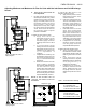
Figure 3. Variable Air Volume
Piping Diagram
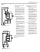
Figure 4. Constant Air Volume
Piping Diagram
TM
ACTUATOR
ACTUATOR
CONTROLLER
T
M
BHi
LO
Hot
Cold
CONTROLLER
M
Lo
T
Hi
B
START
POINT
THERMOSTAT
COLD AIR
HOT AIR
DA
DA
RA
RA
NC
NO
DAMPER
RESET
LO
HI
INCR
Adjustment Tool
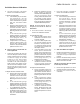
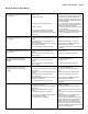
Table 1. Thermostat Switch Settings
Figure 5. Titus II Controller
DA/Cold RA/Hot
8-13 PSI Reset Span
0-8 PSI Min CFM / LO Dial
13-25 PSI Max CFM / HI Dial
RA/Cold DA/Hot
3-8 PSI Reset Span
0-3 PSI Max CFM / HI Dial
8-25 PSI Min CFM / LO Dial