F low bar I N S TA L L AT I O N M A N U A L FlowBar Architectural Linear Diffusers FL-10 FL-15 FL-20 FL-25 FL-30 Redefine your comfort zone. ™ | www.titus-hvac.
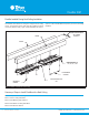
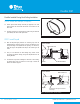
FlowBar IOM FlowBar Installed During Hard Ceiling Installation Titus FlowBar Linear Diffusers are designed to integrate with the ceiling system. The integration process takes place by installing the diffuser concurrently with the ceiling. Figure 1 below summarizes the steps re- quired to install a FlowBar Diffuser System as part of the hard ceiling installation.
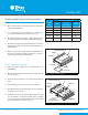
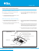
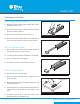
FlowBar IOM FlowBar Installed During Hard Ceiling Installation STEP 1. Identify the Diffuser Border Type There are five different extrusion styles (identified as “Frame Types” in this manual) which are combined to form eight different Border Types. Border Types are identified by combining the two frame styles used i.e. Border Type 16 has one frame #1 and one frame #6. FL-15 HIGH THROW BORDER 22 (Border Type 11 shown) (Border Type 22 shown) BT11]2. is designed for use with hard FRAME 1.
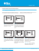
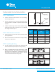
FlowBar IOM FlowBar Installed During Hard Ceiling Installation STEP 2. Construct Ceiling Framework ̷̷ Before installing drywall, a framed opening must be constructed to support the FlowBar Diffuser. ̷̷ It is recommended that the framework be continuous to accommodate the Hard Ceiling Clip spacing requirements. ̷̷ The framing material must be suitable to hold the Diffuser in place when attached with screws through the FlowBar Mounting Clips.
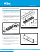
FlowBar IOM FlowBar Installed During Hard Ceiling Installation STEP 4. Attach Diffuser to Ceiling Frame ̷̷ Lift the FlowBar Diffuser into the framed opening and secure the Mounting Clips to the frame with flat head screws as shown in Figure 4. FRAME FRAME ̷̷ If multiple sections of FlowBar are required, repeat previous step by lifting additional sections into the framed opening. Be sure to insert Spline Support Clips-SS1 into the FlowBar ends to insure a tight and aligned connection as shown in Figure 4.
FlowBar IOM FlowBar Installed During Hard Ceiling Installation STEP 6. Attach Inlet Damper (if required) ̷̷ Attach optional Inlet Damper assembly (if supplied) to the Inlet Collar. Position the lever inside the Plenum on the bottom of the Inlet Collar. ̷̷ Install the Inlet Duct on the Plenum Inlet Collar using the methods prescribed by the sheet metal specification. Figure 7. View of Inlet Damper STEP 7.
FlowBar IOM FlowBar Installed During Hard Ceiling Installation STEP 8. Review Installation - (Borders 22 & 55 Only) Before continuing it is recommended that the installer confirm that: ̷̷ The FlowBar Diffuser is secure and straight. ̷̷ Do not run the HVAC system during the finishing procedures. This could cause premature drying of the compounds, making them more prone to cracking. ̷̷ For units longer than twelve feet, a 1/8” gap between sections is recommended to allow for thermal expansion. STEP 9.
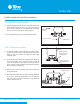
FlowBar IOM FlowBar Installed After Hard Ceiling Installation Attach hanger wire to plenum clips STEP 1. Install Plenums ̷̷ Install Titus model FBP or FBPI Plenum and secure to the building structure using hanger wire. Hemmed Edge of Plenum ̷̷ If Plenum is furnished by others, a hemmed edge inside the bottom of the Plenum sides is required to capture the hanger bracket assemblies. Ceiling Opening Ceiling Figure 11.
FlowBar IOM FlowBar Installed After Hard Ceiling Installation STEP 4. Install Concealed Fasteners ̷̷ Install the QuickClip® Mounting Bracket to the FlowBar Spacer at the desired interval by pushing the #10 x 2-1/2” long screw through the hole in the spacer from the face of the Diffuser. Start the threaded end of the screw into the bracket as shown in Figure 13. Mounting Bracket ̷̷ The recommended spacing is 48” maximum between hangers. #10 x 2 1/2” screw FlowBar Spacer Figure 13.
FlowBar IOM Field Cutting Linear FlowBar STEP 1. Prepare Diffuser for Cutting ̷̷ Working from a table covered with indoor/outdoor carpet, measure the length of Diffuser to be cut. ̷̷ Slide the top Spacer sufficiently to allow for removal of the Pattern Controller(s) as shown in Figure 16. ̷̷ Remove the Pattern Controller(s) as shown in Figure 17. Figure 16.
FlowBar IOM FlowBar Installed In Acoustical Ceiling STEP 1. Install Hanger Clips to Diffuser ̷̷ FlowBar Diffusers with one-slot are supported by sliding Upper Hanger Clips through the top bosses in the FlowBar rails as shown in Figure 20. ̷̷ FlowBar Diffusers with two-slots are supported by sliding Upper Support Hangers through the top bosses in the FlowBar rails as shown in Figure 21. Upper Hanger Clip Figure 20.
FlowBar IOM FlowTee Installation STEP 1. Install Hanger Clips to Diffuser ̷̷ Slide Upper Hanger Clips into Single Slot Diffuser rails or Upper Support Hangers into the top bosses at each end of the Diffuser as described in Acoustical Ceiling Installation, Step 1. STEP 2. Install Diffuser in Ceiling PLENUM HOLES FOR WIRE ATTACHMENT (EACH END) PLENUM CLIPS ̷̷ Install the Diffuser on top of the ceiling grid as shown in Figure 23.
FlowBar IOM ModuFlow Installation STEP 2. Install Hanger Clips ̷̷ Install the Upper Support Hanger (USH) Clips at the clip access area into the upper boss of the Diffuser extrusion and move a clip towards each corner as shown in Figure 25. Hanger Wire ̷̷ Additionally for 9/16” bolt slot grids, install the SC1 Clips into the lower extrusion boss at the access area and move a clip towards each corner. USH Clip STEP 3. Install Diffuser in Ceiling ̷̷ Install ModuFlow unit into ceiling grid.
FlowBar IOM FlowBar Parts List Description: Upper Hanger Clip Model: UHC-10, -15 or -20 Application: Use with One-Slot models FL-10, -15 or -20 any border type, except Border Type 77. Clip inserts into extrusion boss and hanger wire threads through hole in clip to support FlowBar Diffuser.
FlowBar IOM FlowBar Parts List Description: Wall Clip Model: WC3 Application: Use with Frame 1 install Diffuser flush against side wall. Insert a clip into the extrusion boss on the outside of the Diffuser frame. Attach clip to Framing Member with flat head screw. Clips should be spaced at 10” intervals. Quantity per Bag: 28 pieces Description: Wall Clip Model: WC4 Application: Use with Frame 6 or 7 install Diffuser flush against side wall.
Titus FlowBar architectural linear diffuser system maximizes engineering performance without sacrificing aesthetic considerations for the designer. FlowBar’s outstanding performance allows higher airflows than conventional linear diffusers, with lower noise levels, making it ideal for high profile designs. FlowBar The FlowBar was the first supply diffuser in the industry designed specifically for the architect.