Titus Alpha BAC-8007, BAC-8207 Dual-Duct VAV Controllers Installation Guide
BAC-8007 and BAC-8207 VAV Controllers Section 1 About the controllers Specifications ........................................................................................................................ 5 Safety considerations .......................................................................................................... 7 Section 2 Installing the controller Setting the rotation limits ................................................................................................. ..
SECTION 1 About the controllers This section provides a description of the Titus Alpha BAC-8007 and BAC-8207 VAV controllers. It also introduces safety information. Review this material before installing or operating the controllers. The BAC-8007 and BAC-8207 are native BACnet, direct digital controllers designed for VAV terminal units. An integrated actuator and the supplied programs make these ideal controllers for temperature setback, overrides, reheat and other HVAC sequences.
About the controllers Specifications Outputs, analog Key features Connector Conversion Output voltage Output current Outputs, binary Key features Conversion Connector Output range Communications BACnet MS/TP Sensor jack Supported objects Control Basic PID loop objects Value objects 2 Output short protection Configured as BACnet analog objects. Standard units of measure Spade connectors, 0.
BAC-8007 and BAC-8207 VAV Controllers Air flow sensor features About the controllers Specifications Configured as BACnet analog input object. CMOS differential pressure 0-2 inches of water (0-500 Pa) measurement range. Internally linearized and temperature compensated. Span accuracy 4.5% of reading. Barbed connections for 1/4 FR tubing. Range dependent upon DP pickup, tubing size/ length and connections. Actuator specifications 40 in-lb. (4.
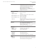
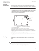
About the controllers Specifications Dimensions A B C D E F G Table 1-1 BAC-8000 dimensions 6 A B C D E F G 6.53 in. 4.89 in. 4.25 in. 0.77 in. 6.00 in. 2.14 in. 1.92 in.
About the controllers Safety considerations Safety considerations Titus assumes the responsibility for providing you a safe product and safety guidelines during its use. Safety means protection to all individuals who install, operate, and service the equipment as well as protection of the equipment itself. To promote safety, we use hazard alert labeling in this manual. Follow the associated guidelines to avoid hazards. Danger Danger represents the most severe hazard alert.
SECTION 2 Installing the controller This section provides important instructions and guidelines for installing the BAC-8007 and BAC-8207 controllers. Carefully review this information before installing the controller. Installing the VAV controller includes the following topics that are covered in this section.
Installing the controller Setting the rotation limits Setting the rotation limits KMC Controls Before mounting the controller, set the rotation limits with the supplied stop screw. Installing the stop screw limits the shaft rotation to either 45 or 60 degrees. Caution Before setting the rotation limits on the controller, refer to the damper position specifications in the VAV control box to which the controller will be attached.
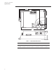
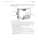
BAC-8007 and BAC-8207 VAV Controllers Installing the controller Mounting Mount the controller close enough to the pitot tubes to keep the tubing length to a minimum. In typical installations the controller’s inputs and sensors are within 24 inches of each other. Status LEDs Gear disengagement button Mounting tab Drive hub and V-bolt Mounting bushing Airflow sensor inputs Illustration 2-2 Controls and indicators Mount the controller as follows: 1.
Installing the controller Connecting inputs Connecting inputs The BAC-8007 and BAC-8207 controllers have preconfigured analog inputs to support the supplied programs. The inputs cannot be changed to binary or accumulator inputs. Only six inputs have externally available physical terminals. All of the inputs are preconfigured for the application programs supplied in the dual-duct controllers and are listed in Table 2-1.
BAC-8007 and BAC-8207 VAV Controllers Installing the controller Connecting inputs Primary Duct Pressure The primary duct pressure input is an internal measurement from the airflow sensor. Secondary Duct Pressure The secondary duct pressure input is an analog input preconfigured to connect to the P Out terminal of a TSP-8000 series actuator for dual-duct operation. The TSP-8000 P Out represents actual airflow detected by the TSP-8000 airflow sensor.
Installing the controller Connecting outputs Connecting outputs The BAC-8007 and BAC-8207 controllers have eight preconfigured outputs to support the supplied programs. Only six have externally available physical terminals. All of the outputs are preconfigured for the application programs supplied in the in the dual-duct controllers and are listed in Table 2-2.
BAC-8007 and BAC-8207 VAV Controllers Installing the controller Connecting outputs Fan Speed Controls the speed of a variable speed fan if the controller is set up for fan operation. Illustration 2-6 Fan speed output Fan Start/Stop The fan start output is preconfigured to either start or stop a single speed fan or enable a multispeed fan. The output is a triac that can switch up to 1 ampere at 24 volts AC.
Installing the controller Connecting to sensors Connecting to sensors Connect any of the following sensors to the RJ-45 thermostat and sensor jack. STE-8001 STE-8201 STE-6010 STE-6014 STE-6017 Link the controller to sensors with standard straight-through Ethernet cables up to 75 feet long. See the installation guide supplied with the sensors for complete sensor installation instructions.
BAC-8007 and BAC-8207 VAV Controllers Connecting to an MS/TP network Installing the controller Connecting to an MS/TP network The BAC-8000 series controllers are BACnet MS/TP compliant controllers. Connect them only to a BACnet MS/TP network. See Application Note AN0404A, Planning BACnet Networks for additional information about installing controllers.
Installing the controller Connecting to an MS/TP network Ground shield only at one end of the segment. Redundant network wiring for increased reliability Illustration 2-11 MS/TP network wiring Note The MS/TP terminals are labeled -A, +B and S. The S terminal is provided as a connecting point for the shield. The terminal is not connected to the ground of the controller. When connecting to controllers from other manufacturers, verify the shield connection is not connected to ground.
BAC-8007 and BAC-8207 VAV Controllers Installing the controller Connecting to an MS/TP network End of line termination switches The controllers on the physical ends of the EIA-485 wiring segment must have end-of-line termination installed for proper network operation. Set the end-of-line termination to On using the EOL switches. Set end-of-line termination to On in these controllers only.
Installing the controller Connecting an airflow sensor Connecting an airflow sensor An airflow sensor is incorporated as one of the inputs to the controller. Remove the plugs and connect the tubing from the pitot assembly to the airflow sensor inputs next to the drive hub. (See Illustration 2-14). The airflow sensor is programmed as Input 1. Total airflow (high) Static airflow (low) Illustration 2-14 Airflow sensor inputs Connecting power The controllers require an external, 24 volt, AC power source.
BAC-8007 and BAC-8207 VAV Controllers Installing the controller Connecting power Connect the 24 volt AC power supply to the power terminal block on the lower right side of the controller near the power jumper. Connect the ground side of the transformer to the ground terminal and the AC phase to the phase ~ terminal. Power is applied to the controller when the transformer is powered.
Installing the controller Dual-duct connections Dual-duct connections The BAC-8007 and BAC-8207 controllers are configured by the manufacturer for dual-duct operation. Connect the controllers to a TSP-8000 series actuator as shown in the illustration Dual-duct wiring diagram on page 24.
SECTION 3 Setting up dual-duct controllers The topics in this section cover setting up the BAC-8007 and BAC-8207 for dual-duct VAV operation. These are advanced topics for controls technicians and engineers. The BAC-8007 and BAC-8207 dual-duct VAV controllers are set up by the manufacturer to operate as soon as power is applied and connected as described in the section Installing the controller on page 11.
Setting up dual-duct controllers Setting temperature setpoints Setting temperature setpoints The space temperate setpoints listed in Table 3-1, “Temperature setpoints,” on page 26 are used to control the controller VAV operation. The temperature setpoints have default values, but may be manipulated depending on which type of wall sensor is connected to the controller. Occupied cooling and heating setpoints These setpoints are user controlled space setpoints that originate from an attached sensor.
BAC-8007 and BAC-8207 VAV Controllers Setting airflow setpoints Setting up dual-duct controllers Setting airflow setpoints The airflow setpoints are limits for VAV unit operation. All values are entered by a controls technician. Minimum and maximum cooling airflow Sets the airflow limits through the VAV unit when in the cooling mode. Minimum and maximum heating airflow Sets the airflow limits through the VAV unit when in the heating mode. Minimum and maximum fan speed Sets the limits on the fan speed.
Setting up dual-duct controllers Setting the VAV terminal unit parameters Setting the VAV terminal unit parameters Terminal unit parameters set basic operating parameters and enable options such as reheat and series or parallel fan operation. Reheat Enables and sets the type of reheat. Choose from the available types of reheat from the following list. None—Reheat is not enabled. Staged—Not available on dual-duct models) Modulating—The reheat output varies from 0-10 volts.
BAC-8007 and BAC-8207 VAV Controllers Setting up local lighting control Setting up dual-duct controllers Setting up local lighting control Automatic local lighting can controlled by the motion sensor in an STE-8201 connected to the controller. Local lighting is set up either with software or an attached STE-8201. Lighting control enable When enabled, local lights will be turned on or off based on motion detected by an STE-8201.