Titus Alpha VAV Controller Cooling Only BAC-8001 Installation Guide
BAC-8001 and BAC-8201 VAV Controllers Contents Section 1 About the controllers Specifications ........................................................................................................................ 5 Safety considerations .......................................................................................................... 7 Section 2 Installing the controllers Setting the rotation limits ..............................................................................................
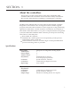
SECTION 1 About the controllers This section provides a description of the Titus Alpha BAC-8001 and BAC-8201 VAV controllers. It also introduces safety information. Review this material before installing or operating the controllers. The BAC-8001 and BAC-8201 are native BACnet, direct digital controllers designed for VAV terminal units. An integrated actuator and the supplied programs make these ideal controllers for basic single-duct cooling and heating applications.
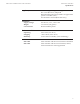
About the controllers Specifications Communications BACnet MS/TP Sensor jack Supported objects Control Basic PID loop objects Value objects EIA–485 operating at rates up to 76.8 kilobaud. Removable screw terminal block.
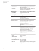
BAC-8001 and BAC-8201 VAV Controllers Regulatory About the controllers Specifications UL 916 Energy Management Equipment FCC Class B, Part 15, Subpart B BACnet Testing Laboratory listed as an application specific controller (ASC). UL 864 smoke controls (BAC-8201 only) Installation Supply voltage Weight Case material 24 volts AC, -15%, +20% 5 VA 13.
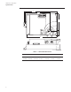
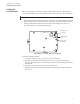
About the controllers Specifications Dimensions A B C D E F G Table 1-1 BAC-8000 dimensions 6 A B C D E F G 6.53 in. 4.89 in. 4.25 in. 0.77 in. 6.00 in. 2.14 in. 1.92 in.
About the controllers Safety considerations Safety considerations Titus assumes the responsibility for providing you a safe product and safety guidelines during its use. Safety means protection to all individuals who install, operate, and service the equipment as well as protection of the equipment itself. To promote safety, we use hazard alert labeling in this manual. Follow the associated guidelines to avoid hazards. Danger Danger represents the most severe hazard alert.
SECTION 2 Installing the controllers This section provides important instructions and guidelines for installing the BAC-8001 and BAC-8201 controllers. Carefully review this information before installing the controllers. Installing a VAV controller includes the following topics that are covered in this section.
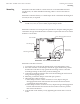
Installing the controllers Setting the rotation limits Setting the rotation limits Before mounting the controller, set the rotation limits with the supplied stop screw. Installing the stop screw limits the shaft rotation to either 45 or 60 degrees. Caution Before setting the rotation limits on the controller, refer to the damper position specifications in the VAV control box to which the controller will be attached.
BAC-8001 and BAC-8201 VAV Controllers Mounting Installing the controllers Mounting Mount the controller inside of a metal enclosure. To maintain RF emissions specifications, use either shielded connecting cables or enclose all cables in conduit. Mount the controller directly over the damper shaft. A minimum shaft length of 2.0 inch (51 mm) is required. Note The controller is designed to directly mount to 3/8 to 5/8 inch (9.5 to 16mm) round or 3/8 to 7/16 (9.5 to 11mm) square damper shafts. .
Installing the controllers Connecting inputs Connecting inputs The BAC-8001 and BAC-8201 controllers have preconfigured analog inputs to support the supplied programs. The inputs cannot be changed to binary or accumulator inputs. Only one input has an externally available physical terminal. All of the inputs are preconfigured for the application programs supplied in the controllers and are listed in Table 2-1.
BAC-8001 and BAC-8201 VAV Controllers Connecting outputs Installing the controllers Connecting outputs The BAC-8001 and BAC-8201 controllers have two preconfigured outputs to support the supplied programs. The outputs are programmed run the integrated actuator in either a clockwise or counterclockwise direction. No external output connections are available.
Installing the controllers Connecting to an MS/TP network Connecting to an MS/TP network The BAC-8000 series controllers are BACnet MS/TP compliant controllers. Connect them only to a BACnet MS/TP network. See Application Note AN0404A, Planning BACnet Networks for additional information about installing controllers.
BAC-8001 and BAC-8201 VAV Controllers Installing the controllers Connecting to an MS/TP network Ground shield only at one end of the segment. Redundant network wiring for increased reliability Illustration 2-6 MS/TP network wiring Note The MS/TP terminals are labeled -A, +B and S. The S terminal is provided as a connecting point for the shield. The terminal is not connected to the ground of the controller.
Installing the controllers Connecting to an MS/TP network End of line termination switches The controllers on the physical ends of the EIA-485 wiring segment must have end-of-line termination installed for proper network operation. Set the end-of-line termination to On using the EOL switches. Set end-of-line termination to On in these controllers only. Illustration 2-7 End of line termination Illustration 2-8 shows the position of the BAC-8000 End-of-Line switches associated with the MS/TP inputs.
BAC-8001 and BAC-8201 VAV Controllers Connecting an airflow sensor Installing the controllers Connecting an airflow sensor An airflow sensor is incorporated as one of the inputs to the controller. Remove the plugs and connect the tubing from the pitot assembly to the airflow sensor inputs next to the drive hub. (See Illustration 2-9). The airflow sensor is programmed as Input 4.
Installing the controllers Connecting power Connecting power The controllers require an external, 24 volt, AC power source. Use the following guidelines when choosing and wiring transformers. Use a Titus Alpha Controls Class-2 transformer of the appropriate size to supply power to the controllers. Titus recommends powering only one controller from each transformer. . Do not run 24 volt, AC power from within an enclosure to external controllers.
BAC-8001 and BAC-8201 VAV Controllers Application drawing The BAC-8001 and BAC-8201 controllers are configured by the manufacturer for single-duct cooling or heating VAV control. Connect the controller as shown in the illustration BAC-8001 and BAC-8201 application on page 21.
SECTION 3 Setting up VAV controllers The topics in this section cover setting up the BAC-8001 and BAC-8201 for controllers for VAV operation. These are advanced topics for controls technicians and engineers. The BAC-8001 and BAC-82018001 VAV controllers are set up by the manufacturer to operate as soon as they are connected to external equipment and power is applied. Installation and connection instructions are covered in the section Installing the controllers on page 11.
Setting up VAV controllers Setting temperature setpoints Setting temperature setpoints The space temperate setpoints listed in Table 3-1, “Temperature setpoints,” on page 24 are used to control the controller VAV operation. The temperature setpoints have default values, but may be manipulated depending on which type of wall sensor is connected to the controller. Occupied cooling and heating setpoints These setpoints are user controlled space setpoints that originate from an attached sensor.
BAC-8001 and BAC-8201 VAV Controllers Setting airflow setpoints Setting up VAV controllers Setting airflow setpoints The airflow setpoints are limits for VAV unit operation. All values are entered by a controls technician. Minimum and maximum cooling airflow Sets the airflow limits through the VAV unit when in the cooling mode. Minimum and maximum heating airflow Sets the airflow limits through the VAV unit when in the heating mode.