
Product Manual


18 AirCoat
GB
Servicing
8. Servicing
8.1 Servicing the Air Motor
The Air Motors require a normal mantenance inspection at 1500
hours of service on the non-circulating models.
ServiceprocedureincludesreplacementoftheMotorServiceKit(see
next page for part numbers). It is suggested that one Motor Service
Kitbekeptonhandfornormalmaintenanceandemergencyrepairs.
SeenextpageforpartnumbersoftheMotorKit.
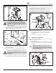
Accessing the Air Motor (Fig. 19)
In order to be able to access the air motor, certain components must
be removed.
i
The piston rod in the uid pump should be in the
lowest-dead center position prior to performing
these steps. The shuto valve can be used to allow
the sprayer to run slowly.
1. Remove all external air and uid hoses from the sprayer.
2. Press the collar on the lower air hose tting (1) and remove
the air hose from the lower air hose tting only.
3. Underneaththefrontshroud,removetheclearairtube(2)
that is connected to the air regulator reservoir.
4. Loosenthecylindercapnut(3)sothatitshandleisoriented
side-to-side and is aligned with the gap in the top shroud (4).
5. Remove the lower screws (5) that secure the motor shroud
assembly (6) to the air motor. Once removed, carefully lift the
entire assembly o of the air motor.
3
6
4
2
5 (x6)
1
Disassembling the Air Motor (Fig. 21)
1. Remove the pin (1) that connects the air motor piston rod
(2)withtheuidpumpdisplacementrod(3).Usinga
wrench on the ats of the displacement rod (3), unthread the
displacement rod from the piston rod.
2. Removethelowerstanchionnuts(4).Gentlylowertheuid
pump (5) away from the air motor.
3. Fullyloosenthecylindercapnut(6).Gentlypullupthe
cylindercapnuttoexposethetriprod(7).Usingapliers,grip
the hex nut (7) on the trip rod, and loosen and remove the
cylinder cap nut from the trip rod.
Attention
Be careful not to damage the outer surface of the
trip rod. A damaged trip rod will cause the air motor
to operate incorrectly.
4. Remove the screws (8) that hold the cylinder (9) and air motor
base(10)together.Becarefulnottolosetheshroudbrackets
or washers that will be removed also. Pull o the cylinder.
Remove the o-ring (31) on top of the motor base.
Attention
When removing the cylinder, remove it straight up.
Avoid tilting. Tilting can damage the cylinder wall.
5. Pull the piston assembly (11) from the air motor base (10). The
piston rod (2) will remain attached within the piston.
6. Check the bearing down in the center of the air motor base. If
worn, replace the motor housing.
i
If the bearing is worn, the entire air motor base will
need to be replaced.
7. Place the ats of the piston rod (2) into a vise to secure the
entire piston rod assembly.
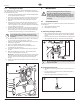
8. Usingascrewdriver,pushdownonthetriprodyoke(g.20,
item 12) and snap the toggles (13) down.
PINCH HAZARD. Keep your fingers clear of the
toggle assemblies (13) when you are snapping the
toggles up or down.
9. Place the tip of a screwdriver between the piston lugs (14)
and below the toggle rocker (15) (place screwdriver at place
marked by asterisk, g. 20).
10. Push forward and up with the screwdriver to compress the
springs on the toggle assembly (13) up and away from the
piston lugs. Remove the springs (16) toggle arms (17), and
toggle pins (18).
i
Place your hand above the toggle assembly as you
perform this step. This will prevent parts from
popping out.
14
15
*
12
13
18
16
18
17
11. Straighten the lockwires (g. 21, item 19) and remove them
from the upper valve nuts (20). Remove the upper valve nuts.
12. Remove the hex nut from the trip rod (7). Remove the trip
rod yoke (12) and the actuator (21). Thread the hex nut (7)
back onto the trip rod to prevent it from sliding down into the
piston rod.
13. Remove the lower valve nuts (22) and remove the inlet valve
poppets (23). Make sure the spring clips (24) are not worn or
damaged, and that they properly guide the actuator (21).
11. Remove the exhaust valve poppets (25) by cutting them with a
side cutter. Remove them from the actuator.