
Product Manual


AirCoat 13
GB
Cleanup Maintenance
5.3 Cleaning the air lter
The air lter blocks any debris or particles that might be present in
the supplied air from the air compressor. It is important that this lter
be checked after every use.
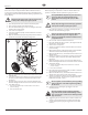
1. Follow the “Pressure Relief Procedure” found in the Operation
section of this manual, section 4.7.
2. Remove the top four screws that secure the front shroud. The
two screws at the bottom front do not need to be removed.
3. After the four top screws are removed, ip open the front
shroud.
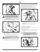
4. Remove the larger tube from the quick-lock tting on the air
inlet tting (Fig. 14, item 1). The other end of the tube can
remain connected. It can be twisted within the bottom tting
so that it will be out of the way.
5. Unthreadthelterbowl(2)thatislocatedunderneaththeair
motorshroud.BecarefulnottolosetheO-ring(3)thatmay
fall out of the bowl. The clear tube may slip o of the tting
on the bottom of the housing. It can be reinstalled later.
i
For model 620 units, press the red lock release on
the gray shroud and turn 1/4 turn counterclockwise
to remove.
6. Unthreadthelterassemblyfromthesprayer.Becarefulnot
to lose the cap (4), spring (5), lter (6) or stem (7).
7. Removeandinspectthelter(P/N0533557,6).Ifdirty,clean
with warm, soapy water.
8. Prior to reassembly, tilt the sprayer on its back.
9. Make sure all parts of the lter are reassembled prior to
reinstallation (g. 14, items 4-7).
10. Thread the entire lter assembly back into its housing in the
sprayer.
11. Make sure the O-ring (3) is in place. Thread the bowl into
position underneath the motor shroud.
Model 620 - with the bowl inside the shroud, insert into place
and turn clockwise until the two parts lock into place. Make
sure the red lock release is facing towards the front of the
sprayer.
12. Flip the front shroud back into place and secure with the four
top screws.
1
2
3
4
5
6
7
6. Maintenance
Before proceeding, follow the Pressure Relief
Procedure outlined previously in this manual.
Additionally, follow all other warnings to reduce the
risk of an injection injury, injury from moving parts
or electric shock. Always unplug the sprayer before
servicing!
6.1 Daily Maintenance
Two daily procedures are required for routine operator maintenance
on this sprayer:
A. Lubricatingtheupperpackings.
B. Cleaningtheinletscreen
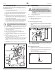
A) Lubricating the Upper Packings
1. Clean out the paint that has seeped past the upper packings
into the packing oil reservoir (g. 15, item 1) above the uid
section.
2. Fillthepackingoilreservoir1/2fullwithPistonLube(P/N314-
480) supplied by the factory. This will extend packing life.
1
i
Do not over-ll the reservoir so that it overows and
drips into the paint.
B) Cleaning the Inlet Screen
1. The inlet screen will clog and must be cleaned at least once a
day.
2. Loosenandremovetheinletscreen(1)fromthebottomof
the metal suction tube.
3. Clean thoroughly with the appropriate solvent.
1