
User Manual


9
E
N
G
L
I
S
H
d. Twisttheair/CO2cylinderclockwiseintotheASAuntilitstops.Usecautionasthe
markerisnowcapableofringafteryouputtheSelectorSwitchinaFiremode.If
youdonothearthefullair/CO2cylinderengage,thepinvalvecouldbetooshortor
thepinvalvesealisdamaged,followtheAir/CO2 Cylinder Removalinstructions
onpage16andtakeyourair/CO2cylindertoa“C5”CertiedAirsmithforinspection
orcontactthecylindermanufacturer.
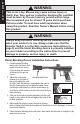
3. Loading the Hopper
Thebarrelblockingdevicemustbeinstalled(seepage4)andtheSelectorSwitchinSafe
mode(seepage6).Formaximumperformance,considerusingaforce-fedhopper.
a. MakesurethattheHopperiscleanandfreeofsharpedgesordebris.Thiskeeps
thepaintballsfrombreakingprematurely,andallowspaintballstofeedintothe
marker’schambersmoothly.
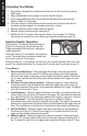
b. OpentheLockingLever(64).InstalltheHopper
intotheFeedNeck(63/62).ClosetheLocking
LevertosecurethehoppertotheFeedNeck.
c. Ifitisnecessarytoadjusttheclampingforce
oftheLockingLever,opentheLockingLever
(Figure4).TurntheAdjustmentKnob(66)
clockwisetotighten(orcounterclockwiseto
loosen)theclampingforceoftheLocking
Lever.ClosetheLockingLeverandcheckthe
clampingforceonthehopper.
d. Withthebarrelblockingdeviceinstalled(page4),andtheSelectorSwitchinSafe
mode(page6),youarenowreadytoloadyourhopperwith.68caliberpaintballs.
Donotforceexcessivenumbersofpaintballsintothehopper.
4. Firing the Marker
Pointthemarkerinasafedirection.Removethebarrelblockingdevicefromthemarker.Move
theSelectorSwitchfromSafemodetoadesiredringposition(ForA).Pullthetriggertore
themarker.
Velocity Adjustment
Eachtimeyouplaypaintball,checkthevelocityofyourpaintballmarkerwithachronograph
(aninstrumentformeasuringvelocity)priortoplayingpaintball.Verifythatthemarker’s
velocityissetbelow300feetpersecond(orlessifrequiredbytheplayingeld).
Toadjustthemarker’svelocity,usetheincluded3/16”Allenwrenchintheholeofthevelocity
adjuster,showninFigure5.
Reducethevelocitybyturningthevelocityadjuster
counterclockwise(asviewedinFigure5).Toincreasethe
velocity,turnthevelocityadjusterclockwise.
NOTE:Forverylowvelocitysettings,itisnecessarytoinstall
theValveSpacer(includedseparatelywiththeCrossover
marker).Followtheinstructionsonpage23.
Figure 4: Feed Neck Detail
Locking Lever
Adjustment Knob
Figure 5: Velocity Adjuster Detail
Velocity Adjuster
- +
- +