
User Manual


21
E
N
G
L
I
S
H
Tippmann
®
Service Department
1-800-533-4831
www.tippmann.com
59
58
54
55
57
56
53
20
52
50
51
49
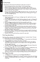
Figure 18: Grip Frame Assembly
WARNING
Do not disassemble this marker while it is pressurized.
Do not pressurize a partially assembled marker.
42
45
19
41
43
48
46
40
44
61
60
39
45
37
48
48
61
61
19
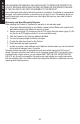
4. Lightly apply Certied Tippmann Grease to the outside surface and inside bore of the
Power Tube (23). Be sure to apply grease to the O-Rings. Thread the Power Tube into
the Air Valve. Use a 1/2” wrench to tighten the Power Tube into the Air Valve.
5. Lightly apply Certied Tippmann Grease to the Front Bolt (34) and Spring (36) and
slide them onto the Power Tube.
6. Insert the entire Spring/Front Bolt/Power Tube/Air Valve/End Cap assembly into the
Crossover receiver and secure by turning the End Cap clockwise until tight.