
User Manual


19
E
N
G
L
I
S
H
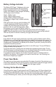
Figure 15: Air Valve Removed from Marker
32
26
23
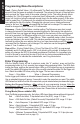
e. Remove the Flex Circuit (43) from
connector J6 (see Figure 13) on the circuit
board by pulling straight out from the
connector.
f. Remove the Solenoid wire harness (40)
from connector J1 on the circuit board by
pulling straight out from the connector.
g. Set the Electronics circuit board aside.
NOTE: Modications to the Electronics
in order to achieve rates of re higher
than 15 bps are not recommended,
and may void the warranty.
4. It is not necessary to remove the Grip
Frame to access the Valve. To remove
the Grip frame assembly, make sure two
screws from the left side Grip Cover are
removed (see step 3). Rotate the Selector
Switch one position clockwise from Safe
mode, then pull straight out from the
Receiver. Use a 1/8” Allen wrench to
remove two Low Head Socket Cap
Screws
(48), from beneath the Grip frame
assembly. Pull straight down on the Grip frame to separate it from the Receiver.
Air Valve Disassembly/Assembly
It is not necessary to remove the Grip Frame to
access and service the Air Valve.
1. Rotate the End Cap (32)
counterclockwise to unscrew it from the
marker. The Air Valve (26) comes out
the back of the Receiver (1).
2. Inspect and clean the exterior of the entire Air Valve/Front Bolt assembly.
3. The Front Bolt assembly consists of the O-Ring (3), Spring (36), and the Front Bolt
Assembly
(34). The O-ring and Spring can be removed from the Front Bolt assembly.
Inspect the O-Ring and Spring and replace if damaged.
4. Use a 1/2” wrench on the ats of the Power Tube (23) to unscrew it from the Air
Valve Body
(26). Inspect the O-Ring (24), and the Bumper Disk (25) and replace if
damaged.
5. To disassemble the Air Valve and End Cap, use your thumb and nger to squeeze the
Air Valve and End Cap together while pushing Valve Pin (33) out of the assembly. The
Air Valve separates from the End Cap Assembly. The Valve Spool Spring (30) should
drop out of the Air Valve. Be sure to retain it.
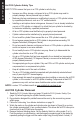
6. Using your thumb, gently push the Valve Spool
Assembly
(29) to remove it from the Air Valve
Body
(26). There are three O-Rings on the Valve
Spool shown in Figure 16. Two of them are Tippmann
part number TA30049 and the third O-Ring (nearest the
opening where the Valve Spool Spring goes in) is part
number TA20003.
7. The End Cap Assembly (32) cannot be disassembled. Inspect four O-Rings (two
#30, one #31, and one #34). Replace only if damaged.
Figure 13: Wire
Harnesses Connectors
J6
J1
Figure 14: Grip Frame Assembly Removal
48
48
Figure 12: Grip Cover
Screws
Figure 16: Valve Spool
SAME