
User Manual


18
E
N
G
L
I
S
H
To maintain your marker in good working condition, inspect, clean, and replace any damaged
parts. Every 8,000 to 10,000 shots, use Certied Tippmann Marker Grease to lightly lubricate
specic areas as instructed in the Crossover Disassembly Instructions. Other than to clean
and grease these specied areas, it is unnecessary to disassemble your Crossover marker
for general maintenance. This maintains your marker in good working condition. Inspect the
air/CO2 cylinder valve O-ring and lubricate it with a little grease prior to attaching the air/CO2
cylinder. After every 50,000 shots, inspect and replace (if necessary) item 3, the front bumper
O-Ring, part number TA20046 and item 28, Bumper Disk, part number TA20077.
Eye Sensors
To clean the eye sensors, remove the eye covers using the included 1/16” allen wrench. Using
a small tool, gently pry the exible circuit away from the receiver. Use a clean, dry cotton swab
to remove any debris, paint, or moisture from the eyes. Clean all debris from the recessed
areas and holes of the receiver using another clean, dry cotton swab. Replace the eye
sensors and the eye covers to the receiver using the same allen wrench.
Storage
Ensure the Selector Switch is in Safe mode (see page 6), and the barrel blocking device is
installed (see page 4). Always remove the air supply (page 16) and unload your marker (page
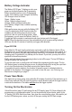
10) when not using your marker. For long term storage (30 or more days), remove the battery
(page 8). Store your marker in a dry area.
When removing your marker out of storage, make sure to keep the Selector Switch in Safe
mode (see page 6) and keep the barrel blocking device installed (see page 4).
Crossover Disassembly Instructions
Set up a workbench with plenty of workspace to make sure no small parts become lost.
Always wear eye protection when performing any marker disassembly or re-assembly.
Refer to the Parts Diagrams for these
instructions (item numbers are in
parentheses).
1. Follow Unloading Your Marker
on page 10 and Air/CO2 Cylinder
Removal
instructions on page 16.
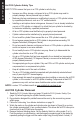
2. To remove the Barrel (72),
simply unscrew the Barrel from
the Receiver. To reinstall it, turn
it clockwise to thread it into the
Receiver. Make sure the O-Ring
(4) stays in the groove inside the
receiver when re-assembling the
barrel to the marker.
When disassembling the marker, pay close attention to how the parts t together to make later
re-assembly easier and accurate. It is not necessary to remove the Grip Frame to access the
Valve.
3. To remove the Electronics Circuit Board (44), use a 5/64” Allen wrench to remove two
screws (61) from both sides of the Grip Covers (left side screws shown in Figure 12).
a. Remove the entire Grip Cover Assembly (60) from the Grip.
b. Remove the Battery from the left side of the Grip.
c. Remove three screws (45) from the Electronics circuit board.
d. From the left side of the Grip, lightly push on the circular capacitor to disengage the
circuit board from the Grip.
4
72
Figure 11: Barrel and O-Ring