
Manual

Carver One Parts List
ITEM
NO. QTY. PT. NO. DESCRIPTION
1 1 TA06053 RightReceiverHalf
2 1 TA06052 LeftReceiverHalf
3 4 98-33 ReceiverDowelPin
4 1 CA-36 SearDowelPin(Black)
5 1 02-35 Sear
6 1 TA02036 SearSpring
7 2 TA02021 ACTLinkageArmGuidePin
8 1 FA-18 BallLatch
9 1 TA06051 FeedElbow
10 1 TA06059 FeedElbowThumbNut
11 1 PL-42C Screw,¼-20x1”SHCS
12 1 PL-42D Nut,¼-20Square(Black)
13 2 98-26 Screw,10-32x¼”BHCS
14 4 CA-02A Screw,6-32x⅜”BHCS
15 8 9-PA Nut,Hex10-32(Black)
16 1 TA06047 LockScrewC-Clip
17 1 98-45 FlatWasherM6(Black)
18 1 TA05004 SplitGrip,Right
19 1 98-01A Bolt,10-32x0.675”
20 2 98-19 ReturnSlideDowelPin
21 1 98-09C GasLine,#4x7⅞”
22 1 TA06003 SplitGrip,Left
23 1 TA06048 Screw,10-32x1.1875”BHCS
24 1 TA06057 USArmyJewel
25 3 TA06015 Screw,10-32x0.840”LHSHCS
26 4 TA09919 Screw,10-32x0.500”LHSHCS
29 1 TA06049 AirSupplyAdapter(ASA)
30 1 CA-08B Nut,10-32
31 1 TA06056 CARVERONENameplate
32 1 CA-14 DriveSpring
33 1 CA-15 GuidePin
34 1 SL2-4 O-ring,FrontBolt
35 1 TA02011 RearBolt
36 1 TA01016 LinkageArm
37 1 98-57 O-ring,EndCap
38 1 98-40 O-ring,Barrel
39 1 CA-27 FrontValveSeat
40 1 PA-28 ValveStemCupSeal
41 1 CA-29 ValveStemCup
42 2 SL2-25 O-ring,ValveSeat
43 1 98-25N ValveBody
44 1 98-56 ValvePlug
45 1 CA-30N ValveStem
46 1 98-32 CompressionSpring
47 1 PA-31A SnapRing
48 1 98-21NR PowerTube
49 1 02-17 FrontBolt
50 1 TA05021 PowerTubePlug
51 1 02-22 VelocitySetScrew
52 1 TA05005 RearBoltPlug
53 1 98-13 RearBoltHandle
54 1 TA06046 Barrel
55 1 TA06060 O-ring,BarrelSleeve
56 1 TA06017 EndCapCover
57 1 TA06006 EndCap
58 2 98-12A O-ring,Valve/RearBolt
59 1 98-36A Trigger
60 1 98-18 TriggerReturnSlide
61 2 98-20 Spring
62 1 98-37N SafetyPin
63 1 98-55 O-ring,Safety(Red)
64 1 FA-07 O-ring,Safety(Black)
PARTS DIAGRAM AND PARTS LIST
theslotsintheRightReceiverHalf(1).TheScrew(11),Flat Washer(17)andNut(12)are
usedtoholdtheHopperintheFeedElbow.Replaceonlyifnecessary.Doallreassemblyinthe
reverseorder.
5. Laythemarkerwiththerightsideontheworkbench.Usetheincludedallenwrenchtoturn
theVelocity Screw(51)allthewayin.SeparatetheReceiver Halves(1and2)byrst
removingthree(longer)Screws(25),andthenfour(shorter)Screws(26)andnallyoneBolt
(19).RetaineightNuts(15)forthesefastenersfromtheRightReceiverHalf.Carefullyliftthe
Left-ReceiverHalftoaccesstheinternalparts.
6. IftheBall Latch(8)needstobereplaced,prytheoldoneoutofthe
RightReceiverHalf.PutthenewBallLatchintotheRightReceiver
Half,orientedasshowninFigure7(circleditem).
7. RemovetheScrew(23)fromtheASA(29).SlidetheASAfromthe
pinintheRightReceiverHalf.BesuretokeeptrackoftheNut(30).
Ifnecessary,youcanunthreadtheASAfromtheGas Line(21).
Useteontapeonthreadsforassembly.
NOTE:Donotremovethegaslinettingunlessitisleakingoryou
needtoreplacethevalve.Ifyoudoremoveit,youwillneedsome
teontapeorpastetoreinstallit.Carefullyhandstartallthreadedparts.Donotovertighten
threadedpartswhenassembling.TofullyremovetheGasLine,unscrewitfromtheValve
Body(43).
The Valve
Disassemblyinstructions:
1. RemovetheEnd Cap Cover(56),andthenremove
theEnd Cap(57).
2. RemovetheGuide Pin(33)andDrive Spring(32).
ThesepartsmustberemovedbeforetheRearBolt
Handlecanberemoved.
3. DisconnecttheLinkage Arm(36)fromtheRear(35)andFront(49)Bolts.
4. SlidetheFrontBoltoffthePower Tube(48)andchecktheO-ring.CleanandoiltheO-ring,or
ifdamaged,replacewithanewone.DothesamewiththeRearBoltO-ring.
5. RemovetheRear Bolt Handle(53)fromtheRear Bolt Plug(52).
6. IfitisnecessarytoremovetheValve,unscrewthetwoValve Lock Bolts(13)fromtheright
sideoftheReceiver.UseawrenchtoslowlyunscrewtheGas Line(21)ttingfromtheValve.
Oncethettingisremoved,theValve(43)slidesoutthebackofthePowerTube.Besureto
setthepartsontheworkbench.Inspectandcleantheexteriorofallassemblies.
NOTE:ChecktheexternalValveO-ring(58)andifdamaged,replacewithanewone.Ifthe
O-ringisdamaged,yourmarkerwillnotfunctioncorrectly.
7. Inspectandlubricatetheseinternaldriveassemblyparts:
• Front Bolt O-ring(34)
• Rear Bolt O-ring(58,seeFigure8)
• Linkage Arm(36)
• Drive Spring(32)andGuide Pin(33)
8. InspectandlubricatetheBarrel O-ring(38)andtheair/CO2cylindervalveO-ringwithafew
dropsofoil.
Reassembly:
1. ReinstalltheValveintothePowerTube.InsertthecleanedandoiledValveintothePowerTube
andaligntheholesoftheValveandPowerTube.Applyteontapeorthreadpasteonthreadsof
theGasLinettingandcarefullyscrewitintotheValve.Snugwithawrench(donotovertighten
andstripthreadedparts).Wipeoffanyexcesspaste.
2. ReinstallthePowerTube/ValveintotheReceiver.AligntheholesofthePowerTubetothoseof
theRightReceiverHalf.ApplyredLoctite™#271sealanttothreadsoftwoValve Lock Bolts
(13)andtighten-donotover-tightenboltsasyoucouldstripthreads.
The Trigger
Disassemblyinstructions:
1. RemovetheTrigger(59)assemblyfromthereceiver.
BesuretoretainthetriggerreturnSpring(61,located
infrontoftheTrigger,andnotshowninFigure9)
2. ToremovetheTrigger Return Slide(60)andthe
Spring(61),youmustrstremovetheupperReturn
Slide Dowel Pin(20)fromtheTriggerassembly.
3. Whenre-assemblingtheTriggerandSear,make
suretheblackSear Dowel Pin(4)isinthelocation
shown(arrowinFigure10).Theblackpinishardened,
anditiscriticalthatitbelocatedinthisposition.
General Troubleshooting
• Issue—Markerrangeistooshort.
Cause—Notenoughgasisenteringthesystem.
Solution—Checkvelocitywithachronograph.
TurnVelocityAdjustertoincreasevelocity,and
recheckwithachronograph.
• Issue—Markerrangeistoolong.
Cause—Toomuchgasisenteringthesystem.
Solution—Checkvelocitywithachronograph.
TurnVelocityAdjustertodecreasevelocity,and
recheckwithachronograph.
• Issue—Gasleakaroundcylindertoreceiverconnection.
Cause—Wornoutordamagedair/CO2cylinderO-ring.
Solution—Replaceair/CO2cylinderO-ring.
• Issue—Minorgasleak.
Cause—WornordamagedvalveseatO-rings.
Solution—ReplacevalveseatO-ringorreturnvalveifitisdefective.
• Issue—Paintballsfalloutofthebarrel.
Cause—WornorbrokenBallLatch(8).
Solution—ReplacetheBallLatch.
Specications
Model.............................................................................................................TIPPMANN
®
CarverOne™
Caliber................................................................................................................................................ .68
Action........................................................................................... Semi-Automatic(openboltblow-back)
Power...................................................................................................................................... Pneumatic
GasSupply........................................................................... CompressedAir,Nitrogen,orCO2cylinder
HopperCapacity.................................................................................................................188Paintballs
BallFeed.................................................................................................................GravityFeedSystem
FiringRate........................................................................................................... 8paintballspersecond
Trigger.................................................................................................................................... Mechanical
StandardBarrelLength...................................................................................................... 8.5”/21.6cm
Length(withstandardbarrel,nocylinder)...................................................................... 18.75”/47.6cm
EffectiveRange............................................................................................... 150+feet/45.72+meters
Weight(withoutcylinder)..........................................................................................3.245lbs/1.472kg
Finish......................................................................PowderCoatedReceiverandASA,AnodizedBarrel
Velocity—Alwaysmeasureyourmarker’svelocitybeforeplayingpaintballandnevershootat
velocitiesinexcessof300feet/91.44meterspersecond(seeVelocityAdjustmentinstructions).
Warranty and Repair Information
TIPPMANNSPORTS,LLC(“Tippmann”)isdedicatedtoqualitypaintballproductsandoutstanding
service.IntheunlikelyeventofaproblemwiththisTippmannpaintballmarker(“Marker”)and/or
Tippmannaccessories(“Accessories”),Tippmann’scustomerservicepersonnelareavailabletoassist
you.Forcustomerserviceand/orotherinformation,pleasecontact:
TippmannSports,LLC
2955AdamsCenterRoad
FortWayne,IN46803
www.tippmann.com
1-800-533-4831
Warranty Registration
ToactivatetheMarker’sLimitedWarranty,youmustregistertheMarkerwithinthirty(30)daysofthe
dateoforiginalretailsalebyregisteringonlineatwww.tippmann.com.
TheLimitedWarrantyforTippmannAccessoriesdoesnotrequireactivationorregistration;by
registeringtheMarker,youactivatethewarrantyfortheAccessories.
Limited Warranty
Tippmannwarrantstotheoriginalpurchaserthatitwillmakeanyrepairsorreplacementsnecessary
tocorrectdefectsinmaterialorworkmanship,atnochargetoyou,fortheMarkerforaperiodofone
(1)yearfromthedateoforiginalretailsale.Further,Tippmannwarrantstotheoriginalpurchaserthat
itwillmakeanyrepairsorreplacementsnecessarytocorrectdefectsinmaterialorworkmanship,at
nochargetoyou,forTippmannAccessoriesforaperiodofninety(90)daysfromthedateoforiginal
retailsale.AllTippmannasksisthatyouproperlymaintainandcarefortheMarkerandAccessories
(collectively,the“Product”)andthatyouhavewarrantyrepairsperformedbyTippmannoraTippmann
CertiedTechCenter.
ThisLimitedWarrantyisnon-transferable,anditdoesnotcoverdamageordefectstotheProduct
causedby(a)impropermaintenance;(b)alterationormodication;(c)unauthorizedrepair;(d)
accident;(e)abuseormisuse;(f)neglectornegligence;and/or(g)normalwearandtear.
Tippmanndoesnotauthorizeanypersonorrepresentativetoassumeorgrantanyotherwarranty
obligationwiththesaleofthisProduct.
THISISTHEONLYEXPRESSWARRANTYGIVENWITHTHEPURCHASEOFTHISPRODUCT;
ANYANDALLOTHEREXPRESSWARRANTIESAREDISCLAIMED.THEIMPLIEDWARRANTIES
OFMERCHANTABILITYANDFITNESSFORAPARTICULARPURPOSEARELIMITEDTOTHE
APPLICABLELIMITEDWARRANTYPERIODSETFORTHHEREIN,ANDNOWARRANTIES,
WHETHEREXPRESSORIMPLIED,SHALLAPPLYAFTEREXPIRATIONOFSUCHPERIOD.
Somestatesandnationsdonotallowlimitationsonthedurationofimpliedwarranties,sotheabove
limitationmaynotapplytoyou.
ThesoleandexclusiveliabilityofTippmannand/oritsauthorizeddealersunderthisLimitedWarranty
shallbefortherepairorreplacementofanypartorassemblydeterminedtobedefectiveinmaterial
orworkmanship.TIPPMANNSHALLNOTBELIABLEFOR,ANDYOUEXPRESSLYDISCLAIM,
ANYDIRECT,INDIRECT,CONSEQUENTIALORINCIDENTALDAMAGES(COLLECTIVELY,
“DAMAGES”)ARISINGOUTOFTHESALEORUSEOF,ORYOURINABILITYTOUSE,THE
PRODUCT.NOPAYMENTOROTHERCOMPENSATIONWILLBEMADEFORDAMAGES,
INCLUDINGINJURYTOPERSONORPROPERTYORLOSSOFREVENUEWHICHMIGHTBE
PAID,INCURREDORSUSTAINEDBYREASONOFTHEFAILUREOFANYPARTORASSEMBLY
OFTHEPRODUCT.
Somestatesandnationsdonotallowtheexclusionorlimitationofincidentalorconsequential
damages,sotheabovelimitationorexclusionmaynotapplytoyou.Thiswarrantygivesyouspecic
legalrights,andyoumayalsohaveotherrightsthatmayvaryfromstatetostateornationtonation.
Warranty and Non-Warranty Repairs
WhenshippingtheProducttoTippmannforwarrantyornon-warrantyrepair:
1. IfyouhaveaftermarketpartsonyourMarker,pleasetesttheMarkerwithoriginalstockparts
beforereturningtheMarkerforserviceorrepair.
2. Alwaysunloadandremovetheair/CO2cylinderfromtheMarker.Donotshiptheair/CO2
cylinderifitisnotcompletelyempty.
3. ShiptheProducttotheTippmannaddressidentiedabove.
4. Youmustpre-paypostageanddeliverycharges.
5. ProvidethedateofpurchasefortheProduct.
6. Brieydescribetherepairrequested.
7. Includeyourname,returnaddressandatelephonenumberwhereyoucanbereachedduring
normalbusinesshours,ifpossible.
Tippmannmakeseveryefforttocompleteitsrepairworkwithintwenty-four(24)hoursofreceipt.
TippmannwillreturntheProducttoyouviaregulargroundUPS.Ifyouwishtohaveitreturnedusing
afasterservice,youcanrequestNEXTDAYAIRUPSORSECONDDAYAIRUPS,butyouwillbe
chargedforthisserviceandmustincludeyourcreditcardnumberwiththeexpirationdate.Yourcredit
cardwillbechargedthedifferenceinadditionalcostoverregulargroundshippingservice.
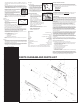
Figure 8: The Rear Bolt Assembly.
53
35
52
32
33
37
58
Figure 9: The Trigger is pulled from the
right receiver half.
20
59
61
60
Figure 10: The black pin is hardened
and must be installed in the
position as shown.
TP04606 01/10Revised 01/26/10
Figure 7: Ball Latch properly
installed into the
right receiver half.