
upduino-readthedocs-io-en-latest


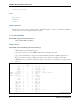
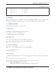
Table Of Contents

UPduino Documentation, Release 0.1
(continued from previous page)
gpio_34 | 19 30 | gpio_3
gpio_43 | 20 29 | gpio_48
gpio_36 | 21 28 | gpio_45
gpio_42 | 22 27 | gpio_47
gpio_38 | 23 26 | gpio_46
gpio_28 | 24 25 | gpio_2
-------------------
1.1.6 Errata
Please note that the silkscreen on the UPduino 3.0 has a bug. The GND and 12MHz clock pins are exchanged. (Pins
41 and 42 in the drawing above). The drawing above is correct and the silkscreen is wrong for these 2 pins.
1.1.7 Blinking an LED
Blinking an LED on the UPduino 3 is its “hello world”
Getting Started
The sample code to blink an LED is built-in to this repository!
https://github.com/tinyvision-ai-inc/UPduino-v3.0
Go to RTL > blink_led folder, to see the example.
Running the Code
The code can easily be run! First, make sure the UPduino is plugged in.
If you want to run the code using icetools (iceprog, specifically), type: make
Then: iceprog rgb_blink.bin
You should see the LED blink!
If you want to use apio, first type: apio init --board upduino3
Then: apio verify to make sure your code works, and then finally:
apio build and apio upload
The LED should blink now!
Making Changes
So the LED is (hopefully) blinking now. If you want to change the code or learn how it works, open the rgb_blink.v
file
.v stands for Verilog, a low-level programming language
The code runs asynchroniously, meaning that multiple lines can run at once on the board.
Anyways, tinker around with the code! Some things to do:
• Make it blink a different color - Maybe white? Yellow? A random hex value?
1.1. UPDuino v3.0: PCB Design Files, Designs, Documentation 5