
Product Overview

EAS Y TO P R OTOT Y P E W I T H
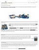
Being so small, you’d think you need to be an expert with a soldering iron to use these things, right? Not at all! We designed these boards to be extremely easy to be
used by hobbyists to embed into your projects. There are multiple prototyping TinyShields available that you can use to interface to your project, including several that
use the same 0.1" spacing as used on the standard Arduino platform for shields. If you’re familiar with connecting up to an Arduino today, you’ll have no problem using
using a TinyDuino.
OPEN SOURCE
TinyCircuits proudly supports open source hardware and have released all the design files for the TinyDuino on our website. If you have a great idea
for a TinyShield or similar Tiny project, you are free to design your own board derived from our design files.
Getting Started You can find in the Getting Started section all the information you need to configure your board, use the Arduino Software (IDE), and start tinker
with coding and electronics.
GETTING STA R T E D
You can find all the information about how to get started connecting up your TinyDuino, installing software and creating your first program in Getting Started with the
TinyDuino tutorial.
TEC H N I CAL DETA I L S
I N P U T A N D O U T P U T
Each of the 14 digital pins can be used as either an input or output. Pins have the same functions as on the Arduino Uno, however the nomenclature is slightly different
to help make it easy to use. Digital pins on the TinyDuino are labelled with an IO prefix, so IO3 on the TinyDuino is equivalent to pin 3 on the standard Arduino Uno. A
number of the pins have alternate functions which are shown below:
Pins IO0 and IO1: These are also the hardware UART serial receive (RX) and transmit (TX) signals. Pin IO0 is RX and pin IO1 is TX. These are used by several of the
TinyShields, namely the USB TinyShield which uses these to program the TinyDuino processor.
Pins IO2 and IO3: These pins can be used as External Interrupts 2 and 3. See the Arduino function attachInterrupt() for details.
Pins IO3, IO5, IO6, IO9, SS (IO10), MOSI (IO11): These pins can provide an 8-bit PWM. See the Arduino function analogWrite() for details.
Pins SS (IO10), MOSI (IO11), MISO (IO12), SCK (IO13): These pins support SPI communication. See the Arduino SPI Library for details.
Pin SCK (IO13): This pin is connected to the LED on the TinyDuino processor board.
Pins A0, A1, A2, A3, A4, A5: These are analog inputs connected 10-bit Analog-to-Digital Converter (ADC) of the microcontroller. See the Arduino function analogRead().
Pins A4 (SDA) and A5 (SCL): These pins can be used for I2C (also called TWI) communication. See the Arduino Wire Library for details.
Pin AREF: This pin can be connected to an external voltage reference for the analog inputs. See the Arduino function analogReference() for details.
Pin RESET: This pin is connected to the reset signal of the microcontroller, bring this signal LOW to reset the processor.
Pins RSV0, RSV1, RSV2: These pins are unique to the TinyDuino plaform and are not currently used, and are reserved for future use.
P O W E R
Power on the TinyDuino platform is handled a bit differently than on the standard Arduino since battery power is allowed. The TinyDuino processor board includes
power switching circuitry to allow it to switch off the VBatt connection when running off of external power. Several power pins that are included on the standard Arduino
system are included on the TinyDuino expansion connector but not connected.
GND: This is the Ground connection for the TinyDuino system
VIN: VIN is the main system voltage for the standard Arduino system and can range from 7-12 Volts. This is only used by the Power TinyShield and not directly connected to any
other TinyShields. If a Power TinyShield is not included in the stack, VIN is not used.