Model: ST910 Installation & Operating Instructions Motion Sensor PIR Light Switch – 2 Wire
1. General Information These instructions should be read carefully in full prior to installation, and retained for further reference and maintenance. 2. Safety • Before installation or maintenance, ensure the mains supply to the light switch is switched off and the circuit supply fuses are removed or the circuit breaker turned off.
• • • • • Time ON Adjustment: 10 seconds (Min) to 15 minutes (Max) LUX Adjustment: 1 ~10lux (Moon symbol) to 1000lux (Sun symbol) Slide Switch: For Automatic and Manual ON/OFF selection DIP Switch: To enable or disable the Manual ON/OFF function. Motion Indication: Red LED turns ON for 1 second when motion detected • CE Compliant • Dimensions – H=86mm, W= 86mm, D=45mm This product requires to be permanently powered which is achieved through the switched live.
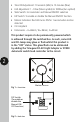
Slide Switch (For Automatic or Manual ON/ OFF operation) Fig 3 – Bottom view 4. Selecting a Location 3 • For indoor use only i.e.: hallways, dining-room, basement, utility rooms and garages, etc. To replace existing one way light switches. • Since the ST910 is sensitive to temperature changes. Avoid mounting directly above heat sources or exposed to direct sunlight. • Avoid mounting the motion sensor switch where it can come into contact with water or rain.
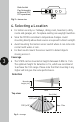
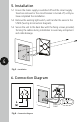
. Installation 5.1 Ensure the mains supply is switched off and the circuit supply fused are removed or the circuit breaker is turned off, until you have completed the installation. 5.2 Remove the existing light switch, and transfer the wires to the ST910 (See Fig 6.Connection Diagram). 5.3 Secure the unit to the back box with the fixing screws provided, forming the cables during installation to avoid any entrapment and cable damage. 4 Fig 5 – Installation 6.
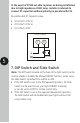
In the event of ST910 not able to power on during installation due to high impedance of LED lamp, installer is advised to connect X1 capacitor (without polarity) in parallel with L/N. Recommended X1 Capacitor value. • X1 0.22uf / 275V or • X1 0.33uf / 275V or • X1 0.39uf / 275V Connection Diagram tion Diagram) L L1 X1 CAP. 5 7.
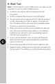
8. Walk Test Note: If the DIP Switch is set to the ON position, also make sure the Slide Switch is set to the AUTO (middle) position. 6 • Set the On-time adjuster fully anticlockwise to the min 10s position. • Set the Lux adjuster fully clockwise to the SUN symbol. • The light switch will now operate during the daytime as well as at night, illuminating your lights for approx. 10 seconds each time. This allows testing to be carried out to establish whether the sensor is covering the required area.
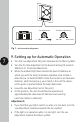
Lux Adjustment 1 ~ 10lux On-time Adjustment min 10s max 15min Fig 7 – On-time and Lux Adjustment 7 9. Setting up for Automatic Operation • Turn the Lux Adjustment fully anti-clockwise to the Moon symbol. • Turn the On-time Adjustment to the desired setting (10 seconds Minimum to 15 minutes Maximum). • When the ambient light level reaches the level of darkness at which you wish the lamp to become operative once motion is detected (i.e.
10. Support Note: If you have any concerns that the intended application of this product does not meet your requirements, please contact Timeguard directly prior to installation. 2 Year Guarantee 8 In the unlikely event of this product becoming faulty due to defective material or manufacture within 2 years of the date of purchase, please return it to your supplier in the first year with proof of purchase and it will be replaced free of charge.
If you experience problems, do not immediately return the unit to the store. Telephone the Timeguard Customer Helpline: HELPLINE 020 8450 0515 or email helpline@timeguard.com Qualified Customer Support Coordinators will be online to assist in resolving your query. For a product brochure please contact: www.timeguard.com 67.058.675 (Issue 1) PS– FEB 2021 Timeguard Limited. Victory Park, 400 Edgware Road, London NW2 6ND Sales Office: 020 8452 1112 or email csc@timeguard.