Time Electronics 5069 Ins-Cal Insulation Tester Calibration System Technical Manual V1.2 20/04/11 Time Electronics Ltd Botany Industrial Estate, Tonbridge, Kent, TN9 1RH Tel: +44(0)1732 355993 Fax: +44(0)1732 770312 Email: mail@TimeElectronics.co.uk Web Site: www.TimeElectronics.
C ontents 1. Supplied Items.................................................................................................. 3 2. G eneral Des c ription ......................................................................................... 4 3. S pec ific ations ................................................................................................... 5 3.1. Technical Specification .................................................................................... 5 3.2.
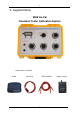
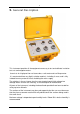
1.
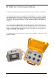
2. G eneral Des c ription This instrument provides all the equipment necessary to test and calibrate insulation test sets and megohm meters. It consists of a high precision resistance box, a volt meter and a milliamp meter. It is constructed from very high insulation materials, including its case, and is fully isolated from any external circuits including the mains supply.
3. S pec ific ations 3.1. Technical Specification Insulation Resistance 3 x Spot values, 100KΩ, 200KΩ, 500KΩ, 1%, Max. Volts 500V 3 x Spot values, 1MΩ, 2MΩ, 5MΩ, 1%, Max. Volts 2KV 9 x 10M ohm 1% Max. Volts 1KV 9 x 100M ohm 1% Max. Volts 6KV 9 x 1G ohm 1% Max. Volts 6KV 10 x 10G ohm 5% Max. Volts 10KV All resistors have a temperature coefficient of 250ppm. Break before make self cleaning switch contacts.
4. Typic al Operation Ins truc tions 5069 Ins-Cal Typical Operation Procedure 1) Fully charge the battery in the 5069. 2) Fully charge the battery in the insulation tester (or fit fresh batteries). 3) Complete the set up procedure for the insulation tester (UUT = Unit Under Test). 4) Connect the selected test leads to the 5069 (these are 4mm recessed sockets). 5) Adjust the pointer at zero on the UUT (meter display, if required). 6) Select O/C VOLTAGE setting on 5069 panel.
5. 5069 Ins -C al P roc edural Notes 1. Always remove the battery charger leads from both instruments before starting set up. 2. Use only the measuring leads supplied with the Unit Under Test or those supplied with the 5069. When checking high resistance values the leads may pick up electrical interference, which can cause a disturbance to the readings obtained. Some manufactures fit a guard connection for use with dedicated leads, this will stabilize the readings. 3.
6. Guarantee & Servicing Guarantee Period This unit is guaranteed against defects in materials and workmanship for a period of one year from its delivery to the customer. We maintain comprehensive after sales facilities and the unit can, if necessary be returned to us for servicing. During this period, Time Electronics Ltd will, at its discretion, repair or replace the defective items.