Time Electronics 1090 Temperature Calibrator Technical Manual V1.2 07/01/11 Time Electronics Ltd Botany Industrial Estate, Tonbridge, Kent, TN9 1RH Tel: +44(0)1732 355993 Fax: +44(0)1732 770312 Email: mail@TimeElectronics.co.uk Web Site: www.TimeElectronics.
C ontents 1. G eneral ................................................................................................................ 3 2. F ront P anel C ontrols .......................................................................................... 4 3. Operating Ins truc tion ......................................................................................... 6 3.1. Turning the unit On/Off ...................................................................................... 6 3.2.
1. G eneral The 1090 is a high performance instrument designed for use in both the lab and field. It simulates and can measure from the most commonly used temperature sensors thermocouples (8 types) and PT100. In addition it can generate and measure mV and mA. Display is via a large, easy to read, 16 character LCD screen. The user interface is simple and intuitive. Increment and Decrement (Inching) keys enable the output to be stepped up or down in 0.1, 1 or 10º C steps, and 0.1,1 or 10 uV/mV/mA..
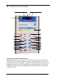
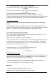
2. F ront P anel C ontrols A B C D E P F Q R G H I J S L T U V W M N X Y K Keypad Primary and Secondary functions Most of the 1090’s keys are dual function. Their primary function is shown in blue on the lower half while the secondary function is shown in red, on the upper half. To access the secondary functions press the ‘SHIFT’ key before the required secondary function key. The display indicates when the ‘SHIFT’ key has been pressed by showing an ‘S’ on the right hand side.
Secondary functions are shown in [ ] A B C D E F G H I J K L M N P Q R S T U V W X Y 4mm Output Terminals 4mm Input Terminals Chassis earth connection 16 digit Liquid Crystal Display Increments output in accordance with user set resolution Decrements output in accordance with user set resolution [Turns unit off] [Selects Type S thermocouple] [Selects Type R thermocouple] [Selects Type K thermocouple] [Selects Type J thermocouple] [Selects Type B thermocouple] [Selects mV] [Selects mA] [Selects uV] In so
3. Operating Ins truc tion 3.1. Turning the unit On/Off To Turn On The unit is powered up by pressing and holding any key for longer than 1 second. On power-up, the software version and (mV/mA/Pt) will be displayed for 2 seconds. The battery voltage is then checked and if below 6.5V a ‘Battery Low’ warning is displayed. If below 6.0V a ‘Battery Dead’ warning appears and the unit powers down.
3.3. Thermocouple Source Select Source mode by pressing ‘SHIFT’ followed immediately by ‘SOURCE’ key. The display will show, Src 0.00mV Thermocouple Selection Select the type of thermocouple that you wish to simulate by pressing the SHIFT’ key immediately followed by the thermocouple type. e.g. SHIFT followed by ‘J’ to select type J. The unit will indicate type and temperature. The display will show, Src Ja xx.
3.5. RTD (PRT) Source Select the PRT mode by pressing the SHIFT’ key immediately followed by ‘PRT’ Meas Pt Over oC Select Source mode by pressing ‘SHIFT immediately followed by ‘SOURCE’ Src Pt –100 oC The display may be changed to read in oF by pressing ‘SHIFT’ + ‘oC/oF’ keys For this mode connect the device to be calibrated to the unit’s OUTPUT terminals. The unit is now ready to simulate a Pt100 probe. Use the ‘Up/Down’ arrow keys to step change the temperature.
3.9. mA Source and 24V Process Loop Drive To select Source mode press ‘SHIFT’ followed immediately by ‘Source’ Scr 0.000mV To select mA Source mode press ‘SHIFT’ followed immediately by ‘mA’ Src 0.000mA Connect the device to be calibrated to the unit’s output terminals Enter the desired mA values using the numbered keys or ‘Up/Down’ arrow keys. It should be noted that the unit can provide a maximum output of 80mA.
Recalling values To recall the stored values the unit must be in ’SOURCE’ mode. 1. Press ‘RECALL’, the display will show, Recall 0-9 > 2. Press the required store location number, the display will show the stored value and it will be sent to the output terminals. 3. Repeat steps 1 and 2 to recall the contents of the other store locations. It should be noted that the store locations only store the numeric value, and not the units. Therefore the correct units i.e.
3.12. Inching (Increment/Decrement) The unit has a general purpose inching function. This adjusts the output in fixed increments of temperature (thermocouples only) or voltage or current. The set-up menu gives a the user a choice of three levels of increment, i.e. 0.1, 1 or 10 for degC/degF, and 1, 10, or 100 uV/uA for voltage/current. The lowest of these represents the highest setting resolution and provides the most precise control of the output.
Inching (Incrementing/Decrementing) - arrow keys This function sets the step size used by the Up/Down arrow keys. Press ‘MENU’ and release 1) Auto-off Yes Use down arrow key to display 4) xx.x o, xxxu Press ‘ENTER’ to cycle between the 3 available settings (0.1, 1.0, or 10 oC ; 1,10 or 100uV/uA) Battery status Displays battery voltage Press ‘MENU’ and release 1) Auto-off Yes Use down arrow key to display 5) Battery x.xxV 3.14. Setting output values between 0.0 and +1.
4. Maintenanc e 4.1. Battery Life and Replacement The 1090 is powered from an internal metal hydride battery pack with a capacity of 5AH. This provides up to 60 hours of continuous operation. The mains recharger will recharge the battery fully in about 11 hours. During operation the battery voltage level is checked once per minute. If below 6.5V, a ‘Battery Low’ warning is displayed. If below 6.0V, a ‘Battery Dead’ warning appears and the unit powers down. 4.2.
5. S pec ific ations MEASURE ACCURACY (0.1 deg C/F resolution) THERMOCOUPLE TEMPERATURE ACCURACY TYPE RANGE deg C Deg C J -200 to 580 0.7 K -200 to –150 2.5 -150 to 750 0.5 -200 to 0 1.5 0 to 400 0.4 -50 to 400 3.0 400 to 1750 1.5 -50 to 100 3.0 100 to 1750 1.5 110 to 1000 3.5 1000 to 1800 1.5 N -100 to 890 0.6 E -50 to 400 0.
SIMULATE ACCURACY (0.1 deg C/F resolution) THERMOCOUPLE TEMPERATURE ACCURACY TYPE RANGE deg C Deg C J -210 to 150 0.15 150 to 1200 0.3 -270 to 190 0.5 190 to 1250 0.4 -200 to 150 0.4 150 to 400 0.5 -50 to 800 0.8 800 to 1750 2.0 -50 to 850 0.9 850 to 1750 2.0 100 to 1200 2.0 1200 to 1800 3.0 -270 to 260 0.5 260 to 1300 1.0 -50 to 1000 0.3 K T R S B N E An additional correction representing the equivalent 1µV should be allowed for stray thermal emf effects.
Millivolt Source 0 to +/- 80mV Accuracy 0.02% of f.s. (16uV) Resolution 5uV Output resistance 10 ohm Note: For output settings below 8mV an increased resolution of 0.5uV is automatically switched in. The accuracy for this part of the span is also increased to +/- 4uV Milliamp Source 0 to 80mA Accuracy 0.02% of f.s. (16uA) Resolution 5uA Maximum load (24V drive) 300R/80mA, 480R/50mA, 1.2K/20mA Inching Three levels of increment, 0.
General Specifications Cold Junction Compensation Resolution: 0.1degC or 0.2degF. Accuracy: 0.1degC/0.2degF at 22degC/72degF. Variation with change in ambient: +/- 0.02 degC/F per degC/F Operating Temperature -10 to 40 degC (15 to 105 degF) Connections 4 off 4mm low thermal screw terminals. Power The internal metal hydride battery pack gives approximately 60 hours continuous operation. The mains re-charger supplied allows full recharge about 11 hours.
6. 1090 C alibration P roc edure Calibration MENU 6 ENTER, enters calibration mode The unit prompts for a password to enter cal mode The code is 982053. There are 8 calibration steps, as follows Pressing CLEAR at any step will skip that step, leaving the calibration data for that step unchanged. Power must not be removed during the calibration process, as this will cause the data check sum to be incorrect. 1) Input +30mV Apply +30.000mV to the input terminals. PRESS ENTER. 1) Input -30mV Apply -30.
If the PRT/Current board is fitted and requires calibration, this must be done after the voltage steps 1-6 above have been performed P50 calibrates the current measure mode, and P51 current source mode. These should be adjusted at full-scale (30mA measure, 80mA source). If the PRT/Current board is recalibrated, you must repeat step 8 above afterwards (use CLEAR to skip past the other steps). Notes on the PRT/Current option board.
7. G uarantee & S ervic ing Guarantee Period This unit is guaranteed against defects in materials and workmanship for a period of one year from its delivery to the customer. We maintain comprehensive after sales facilities and the unit can, if necessary be returned to us for servicing. During this period, Time Electronics Ltd will, at its discretion, repair or replace the defective items.