
User Manual


7
1077 Technical Manual Page | 7
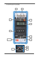
1. Output Terminals
The output current is available on t he two front panel terminals which are suitable for
normal wire compression or 4mm plug inser t ion.
2. Case Terminal
Connected only to the instrument case and is isolated from the circuitry. The case
provides an overall electrostatic screen and can be earthed as required to improve
rejection of noise pick-up.
3. Output On-Off Sw itch
Disconnects the output terminals from the 1077 circ uit r y. The 'Off' position provides
an open circuit on the out put t erminals.
4. Range and Supply On-Off Switch
Four press button switches with interlocking on the 3 range buttons to ens ure that
only one range can be selected at one time.
5. Digit Switch
Four decade thumbwheel switc hes with 0-9 posit ions on each decade.
6. Voltage Limit Indicator
An L.E.D. display which indicates when the 1077 has insufficient voltage across its
output terminals to sink or drive the set c urrent.
Important Note:
Voltages in excess of 40 volts across the output t erminals will cause an
overload condition in the 1077 and the out put fuse will blow.
7. Battery Level Indicator
Located on the side of the inst r ument and continuously monitors the battery volt age.
A minimum mark indicates when t he batteries need recharging.
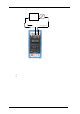
8. Re-charger Socket
Also located on the side of the instrument. The mains r e-charger is a s eparate unit
and the output is via a f lying lead with a non-reversible plug. Charge current is 50
mA and recharge time is 12-14 hours.
9. Load/Line/Source Switch
A three position switch which selects the function of the 1077.
10. LCD M eter
Displays the output current taken when operat ing in 'Line' mode (in Load/Source
mode displays Zero).
11. Out put Voltage Adjustment
Sets maximum open circuit voltage in 'Source' mode and output voltage in 'Line'
mode (normally set for 24V out put).