
User Manual


15
1077 Technical Manual Page | 15
6. Maintenance
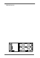
6.1. Dismantling the Instrument
Remove rubber protection boot and then removal of four 2.0mm CSK screws enables the
blue cover to be taken off which provides access to all par ts of the instrument.
The range switch assembly c an be r emoved by disconnecting the 9-pin connector and
removing the two front panel locat ing screws.
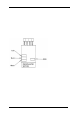
6.2. Fuse Replacement
The power supply and out put fus es are easily accessible on removing the cover panel (6.1).
Fuses are rated at F1A (F1) and F250mA ( F2) and have dimensions 20mm length by 5mm
diameter. The fuses are available fr om Time Electronics Ltd. or your local supplier.
Alternative types of the same dimensions and r ating s may be used.
6.3. Repair
Due to the precision nature of many of the components used in the 1077, they are not
readily available to enable the customer to undertake repairs.
Important Note:
No repair work should be under t aken by the customer w hil e the 1077 is under
warranty. Such work may invalidate the warranty.
Overload conditions can cause the fuses to blow and the following conditions will be
observed:
1. T he instrument is inoperative and the battery level indicator does not operate when the
1077 is switched on. A possible cause is that the power supply fuse F1 is blown (see 6.2).
2. T he battery level indicator displays but no output appears at t he output terminals. A
possible cause is that the output fuse F2 is blown.
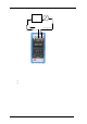
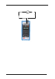
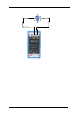
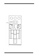
Fuse Location
MODULE
F2 F250m A
J2
BA TTERY P ACK
BA TTERY P ACK
F1 F1A