
User Manual


14
1077 Technical Manual Page | 14
5. Circuit Des cription
5.1. Power Supply
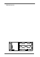
The batteries and power supply circuit r y is located on the bracket which is m ount ed below
the battery level indic at or. Eight AA size rechargeable batteries provide an out put of 9.6
volts D.C. to power a swi t c hed mode regulator which generates all the regulated supplies for
the 1077 and the adjustable out put voltage.
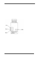
The rechargeable battery is pr ot ected by a miniature fuse mounted on the board. The fuse
is rated at F1A and has dimensions of 20mm length by 5mm diameter.
5.2. Mains Re charger
The mains recharger is a separate unit and enables the 1077 bat teries to be f ully charged in
12-14 hours. An overnight charge is usually adequate. The mains input is 200-240 volts
50/60 Hz standard. 100-120 volts, 50/60 Hz are available but should be specified on
ordering. The plug and socket are shaped to ensure that they cannot be connected in the
wrong polarity.
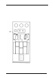
5.3. Circuit Module and Range Switch
The 1077 active circuitry and range switch ar e located on a printed circuit board which is
mounted on the front panel. Connection to the P.C.B. is via a 9 pin connector. The active
circuitry is encapsulated and contains the precision ref erence circuitry and output stage.
Four calibration trimmers are mounted on the P.C. B. (ref. section 6.4).
A replacement procedure should be adopt ed in the case of failure.