Time Electronics 1077 Transim Transducer/Line Simulator Technical Manual V1.1 04/11/10 Time Electronics Ltd Botany Industrial Estate, Tonbridge, Kent, TN9 1RH Tel: +44(0)1732 355993 Fax: +44(0)1732 770312 Email: mail@TimeElectronics.co.uk Web Site: www.TimeElectronics.
C ontents 1. Introduc tion ...................................................................................................... 3 2. S pec ific ations ................................................................................................... 4 3. F ront P anel C ontrols ........................................................................................ 6 4. Operation .......................................................................................................... 8 5. 6.
1. Introduc tion The 1077 is a portable, hand-held instrument designed for the testing and simulation of current transducers. The three operating modes of the 1077 are:- 1. A precision adjustable current load, capable of taking 100mA from a 24V supply. 2. A DC 24 volt supply with a 0-20mA output current display. 3. A precision adjustable current source capable of driving up to 100mA through 250 ohms (or 20mA through 2,000 ohms).
2. S pec ific ations Current Source and Load Current Range: 0 to 100 milliamps in 3 ranges. 0 - 99.99mA in 10 uA steps. 0 - 9.999mA in 1 uA steps. 0 - 999.9uA in 0.1 uA steps. Accuracy: +/-0.02% of setting. +/-0.02% of range. +/-0.02uA Output Stability: Better that 60ppm per deg.C. Voltage Limit: A front panel LED indicator provides indication of insufficient terminal voltage. Drive Voltage: Adjustable from 14 to 40 volts. (Source mode) Drive Power: 2.5 watts maximum.
Page left blank intentionally 1077 Technical Manual Page |5
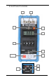
3.
1. Output Terminals The output current is available on the two front panel terminals which are suitable for normal wire compression or 4mm plug insertion. 2. Case Terminal Connected only to the instrument case and is isolated from the circuitry. The case provides an overall electrostatic screen and can be earthed as required to improve rejection of noise pick-up. 3. Output On-Off Switch Disconnects the output terminals from the 1077 circuitry.
4. Operation 4.1. Principle of Operation of the 2 Wire 4/20mA System To fully understand the operation of the 1077 a working knowledge of the 4/20mA system is required. A short explanation follows: The basic requirements for any transducer with remote display is: a) To use as few wires as possible. b) That errors are not introduced into the signal from the transducer by the effects of interference or voltage drop due to lead resistance.
4.2. Checking/Calibrating the Transducer By selecting the 'line' simulation mode on the 1077, the 1077 acts as the 24V D.C. supply and the current meter, any current taken from the 24V across the 1077 terminals will be registered on the L.C.D. meter. The current taken by a transducer can therefore be easily checked by connecting the transducer directly to the 1077 and then reading the current shown on the meter. 4.3.
4.6. Operation as a Current Load (Transducer Simulation) SUPPLY - + I mA LINE As a current load the 1077 Will draw the current set from the line. 1. Turn on 1077, check battery level and select current range nearest to load current required. 2. Select the ‘load’ position of the load/line/source switch. 3. Connect output terminals to the line: • • Positive terminal (red) to positive line. Negative terminal (black) to negative line. 4. Set load current required on the digit switch. 5.
4.7. Operation as a Current Source I mA As a current source the 1077 will supply the set current to the load 1. Check the setting of the output voltage control as in Section 3.1. 2. Turn on and select ‘Source’ mode. 3. Select most suitable range and set output on digit switches. 4. Connect ‘Load’ and turn output switch ON. Note: If V limit LED illuminates the 1077 has insufficient drive voltage to output the current set. See ‘Output Voltage Control’ Section.
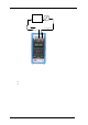
4.8. Operation as a Line Simulator Transducer I mA 24 Volts As a current source the 1077 will supply the set current to the load 24 Volt Line In this mode the 1077 supplies a constant 24V. The current taken by the transducer can be accurately measured on the 1077: 1. Turn on the 1077 and select the line position of the load line source switch. 2. Turn the output switch ON. 3. Read output current on the LCD display.
4.9. Recharging To charge the 1077 first turn off the 1077 then connect the charge to the recharge socket on the end of the 1077. (The connector is polarized to prevent accidental reversal). Plug charger into mains supply. If the 1077 is left ON when recharging the cells will not fully recharge. The 1077 contains Nickel Metal Hydride batteries which are monitored by the battery level indicator at the end of the unit. The unit will take approximately 12-14 hours to fully recharge the batteries.
5. C irc uit Des c ription 5.1. Power Supply The batteries and power supply circuitry is located on the bracket which is mounted below the battery level indicator. Eight AA size rechargeable batteries provide an output of 9.6 volts D.C. to power a switched mode regulator which generates all the regulated supplies for the 1077 and the adjustable output voltage. The rechargeable battery is protected by a miniature fuse mounted on the board.
6. Maintenanc e 6.1. Dismantling the Instrument Remove rubber protection boot and then removal of four 2.0mm CSK screws enables the blue cover to be taken off which provides access to all parts of the instrument. The range switch assembly can be removed by disconnecting the 9-pin connector and removing the two front panel locating screws. 6.2. Fuse Replacement The power supply and output fuses are easily accessible on removing the cover panel (6.1).
6.4. Calibration The 1077 is calibrated when it leaves the factory and should not require further adjustment for at least 12 months unless the circuit module or any of the calibration determining components have been changed. Before attempting recalibration it is important to ensure that the correct equipment is available. Equipment Required: 1. D.C. voltage source power supply for 24V at 100mA. 2. Precision DMM (0.01%) with 100mA, 10mA and 1mA current ranges and 100 volt range. A.
Set the 1077 to Load function with 10mA range and digit switch set to 9999. Connect the 24V supply to the 1077 through the DMM. Check the 1077 takes 10mA from the 24V supply. C. Linearity The linearity of the output is not adjustable and is determined by the precision resistors mounted on the digit switch. These have been selected and adjusted in the factory and should not require further alteration. D. LCD Current Meter F.S.D 1. Set the 1077 to line mode and take 20mA from the output. 2.
7. G uarantee & S ervic ing Guarantee Period This unit is guaranteed against defects in materials and workmanship for a period of one year from its delivery to the customer. We maintain comprehensive after sales facilities and the unit can, if necessary be returned to us for servicing. During this period, Time Electronics Ltd will, at its discretion, repair or replace the defective items.