Time Electronics 1048 Current / Voltage / Loop Calibrator Technical Manual V1.2 30/12/10 Time Electronics Ltd Botany Industrial Estate, Tonbridge, Kent, TN9 1RH Tel: +44(0)1732 355993 Fax: +44(0)1732 770312 Email: mail@timeelectronics.co.uk Web Site: www.timeelectronics.
C ontents 1. 2. Introduc tion .................................................................................................... 3 F ront panel c ontrols and operating modes ................................................. 4 2.1. 2.2. 2.3. 3. Operating Mode: NORMAL ............................................................................ 5 Operating Mode: STEP .................................................................................. 5 Operating Mode: RAMP ...............................
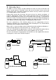
1. Introduc tion The 1048 is a current, voltage, and loop calibrator that meets the needs of R&D labs and process control engineers. It provides source and measure functions in three current and voltage ranges, plus a transmitter simulator/sink function. Accuracy is 0.02% of span and it has 4.5 digit (0.005% of span) resolution. Output modes include steps and ramps. No menus to learn, just switches and buttons.
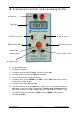
2. F ront panel c ontrols and operating modes A. Terminals B. Display C. OFF/V/mA switch G. Range switch H. Increment (INC) D. Decrement (DEC) E. Multi-Turn I. Function switch Output Control F. Output switch A. Input/Output terminals B. 4.5 Digit LCD Display. C. 3 position switch for ON/OFF( OFF), Volts (V), Current (mA). D. Push button for fine decreasing (DEC) of the output. E. 10 turn control for coarse output adjustment F. 3 position switch, normal (NORM), zero (OFF), reverse (REV) output.
The unit has three principal operating modes: 2.1. Operating Mode: NORMAL Provides manual operation of the standard measure and source functions for both voltage and current. A transmitter simulation/sink (TX SIM) function is also included for loop test and calibration. The internal power supply can also be used to provide the drive voltage to passive process control transmitters and sensors. This allows them to be calibrated without the need for the loop power to be connected. 2.2.
3. Normal Operating Mode 3.1.1. Resolution high/low The unit has a unique method of changing the display resolution when values greater than the conventional 19999 (4.5 digit) display are used. This feature allows the units ranges to be extended by 10% above the commonly used 0.2/2.0/20 full scales. Calibration of values just above these figures is now possible. This will be found particularly useful with 4 - 20mA transducers where they are slightly over scale but are still within specification.
Source function (V & mA) The NORM position outputs signals in the polarity indicated by the terminals. The REV position reverses the polarity. When outputting voltage or current, the OFF position disconnects the output signal and places an open circuit on the output terminals. The display will read zero. PS When the switch is in the REV position it should be noted that the display does not place a – annunciator before the value.
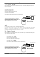
3.3. Measure – Current The unit measures current in three selectable ranges, 0 to 0.22mA (displayed in uA), 0 to 2.2mA and 0 to 22mA (plus over-range to 70mA). SPECIAL NOTE: Although the top range is nominally 22mA span, it can be safely used to measure current up to 70mA.
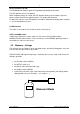
3.5. Source – Voltage The unit outputs voltage from 0 to 22V in three ranges, 0 to 0.22V (displayed in mV); 0 to 2.2V and, 0 to 22V. Set function switch to SRC Set OFF/V/mA switch to V Set range switch to the desired range Set output switch to NORM Set multi-turn output control to minimum (anticlockwise) Receiving instrument Connect the unit to the process instrument observing correct polarity and adjust the multi-turn output control for coarse control and INC and DEC buttons for fine control.
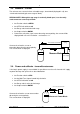
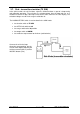
3.7. Sink - transmitter simulator (TX SIM) In the Sink function, the unit simulates a process field transmitter as part of a loop testing and calibration operation. The unit takes its excitation power from the loop and acts as a variable resistance to adjust the loop current to the value shown on the units display. The excitation voltage must be in the range 3 to 50 volts dc. The NORM/OFF/REV switch in not functional in the SINK mode.
4. A dditional Operating Modes These modes are designed to automate and speed up the process of testing and calibration. The STEP mode allows simplified calibration. It provides output steps of fixed value. Three choices are available, a) 5 point calibration; 4, 8 ,12, 16, 20 mA b) 11 point calibration; 1,2,3,4,5,6,7,8,9,10 V c) 21 point calibration; 1,2,3,4,5…18,19,20 mA or V The a) and b) choices are the defaults. The c) choice is obtained by powering up the unit while pressing the DEC button.
4.2. STEP – Automatic This function provides a method of automatically stepping through the fixed output values. • • • • • Set function switch to SRC Set OFF/V/mA switch to the desired units (V or mA) Set range switch to the desired range. Set output switch to NORM Simultaneously press INC and DEC buttons. The word “CONTINUITY” will appear on the display and the reading will go to zero.
5. Operating P rec autions 5.1. Display The LCD display should not be exposed to strong sunlight for prolonged periods. 5.2. Usage & Storage Temperature Operating: -10 to +50 degC (14 to 120 degF) Storage: -30 to +70 degC (-22 to 160 degF) Humidity The operating and storage relative humidity limits are 10 to 90% non-condensing at 25 deg C (77 deg F) 5.3. Automatic power down disable If the unit is not operated for 15 minutes it will automatically power down to conserve the battery life.
6. P ower S upplies 6.1. Auto-power down If the unit is not used for 15 minutes, it will automatically power down to conserve the battery life. This feature can be disabled by holding down the INC button whilst switching on the unit. 6.2. Battery Life The unit is powered by a PP3 (Alkaline) battery that lasts approximately 15 hours of normal operation. Continuous operation on current will shorten the battery life. The unit will indicate ‘Low Battery’ when the battery needs changing.
7. Maintenanc e 7.1. Recalibration Calibration equipment required: A) A precision DC voltage calibrator with an accuracy of 0.01% or better. Examples of suitable instruments are Time Electronics’ 1017, 5018, 5025 or 5051. B) DMM with accuracy of 0.01% or better. Examples of suitable instruments are Time Electronics’ 5075, or 5065. Note: It is advisable to use leads with low thermal emf connections. This will ensure that stray thermal emfs do not cause errors when calibrating the low voltage range (.
7.2. Dis-Assembling the Unit A. Ensure that the unit is switched off before removing the rear panel which slides out. Note: The plastic cover retaining clip will need to be removed prior to sliding cover off, refit when reassembled. B. Remove the cap on the multi-turn control knob by levering it off with a fine bladed screwdriver or similar tool. C. Remove the collet nut (inside the knob). Use a suitable split head screwdriver or small long nosed pliers. D.
7.3. Trimmer Locations P3 P7 P9 P5 P8 P6 P2 P4 V1.
7.4. Measure Function Calibration 1) a) Switch on the unit while holding down the ‘Decrement-DEC’ button (left side). Select the ‘V’ position. b) Select ‘MEAS’ on the Function switch. c) Select ‘0.22’ on the Range switch. d) Select ‘NORM’ on the Output switch. Note: It may be necessary to check the required switch positions by looking at the markings on the front panel. 2) Connect the precision DC voltage calibrator to the unit’s terminals and select zero output. Check that the unit is displaying 00.
7.5. Step Mode Calibration 1) a) Select ‘SRC’ on the Mode select switch. b) Select 0.22 on range switch. c) Select ‘Norm’ on output switch. 2) Enter the step mode by pressing the ‘Inc’ and ‘Dec’ buttons simultaneously. The ‘CONTINUITY’ legend will then show on the top of the right side of the display. Press the ‘DEC’ button twice. Note: Make sure that the unit was switched on with the ‘DEC’ button held down. 3) Adjust P9 for 100.0 on the display.
7.7. Re-Assembling the Unit Re-assemble the unit in the reverse order as in 5) through to 1). Please note that there is some difficulty in returning the printed circuit board assembly to its correct position in the case. It is important to initially position it so that the external supply socket (the terminal end) is adjacent to its hole in the case.
8. S pec ific ations DC Current -Source and Measure Span: 0 - 22mA (Source), 0 - 22mA and 22-70mA (Measure) Source Accuracy: 0.02% of range Measure Accuracy: as source 0-22mA, above 22mA 0.05% Resolution: 1uA (0 - 19.999mA), 10uA (above 20mA) Span: 0 - 2.2mA Accuracy: 0.02% of range Resolution: 0.1uA (0 - 1.9999mA), 1uA (above 2mA) Span: 0 - 220uA Accuracy: 0.05% of range Resolution: 0.01uA (0 - 199.99uA), 0.1uA (above 200uA) Max source load: 1100ohms@20mA. Max drive, 22V Max measure load: 0.22, 2.
Sink (TX SIM) 2 wire transmitter simulation: External excitation voltage, 3V min, 50V max. The current sink levels are adjustable with accuracies as in the three mA source ranges shown on page 21. Output Steps 5 fixed steps for I output 4, 8, 12, 16 & 20 mA 11 fixed steps for V output 0,1,2...10V 21 fixed steps for V & I output 0,1,2…...20 Stepping can be done manually or can be set to run automatically up and down continuously with adjustable speed control (1-10 sec/step).
9. G uarantee & S ervic ing Guarantee Period This unit is guaranteed against defects in materials and workmanship for a period of one year from its delivery to the customer. We maintain comprehensive after sales facilities and the unit can, if necessary be returned to us for servicing. During this period, Time Electronics Ltd will, at its discretion, repair or replace the defective items.