Time Electronics 1044 Voltage and Current Calibrator Technical Manual V1.1 09/01/11 Time Electronics Ltd Botany Industrial Estate, Tonbridge, Kent, TN9 1RH Tel: +44(0)1732 355993 Fax: +44(0)1732 770312 Email: mail@TimeElectronics.co.uk Web Site: www.TimeElectronics.
C ontents 1. Introduc tion ........................................................................................................ 3 2. S pec ific ations ..................................................................................................... 4 3. Operation of the 1044 ........................................................................................ 6 3.1. Preliminary ..........................................................................................................
1. Introduc tion The 1044 has been designed to offer solutions in many applications from the R&D lab to the service engineer; in fact anywhere an accurate and low cost calibrator is needed. We have used our experience in designing instrumentation to bring you the most versatile and practical calibrator yet. The 1044 can source and measure voltage and current in one compact unit and the 0.05% accuracy is ideal for simulation and calibration in most engineering applications.
2. S pec ific ations RANGES Voltage Source Range Resolution Accuracy 0 - 200mV 100uV ± 0.05% 0 - 2V 1mV + 0 - 20V 10mV ± 2 Counts O/P Current T/C per °C 20mA ± 150ppm Voltage Measure Range Resolution Accuracy O/P Voltage 0 - 200mV 100uV ± 0.05% <2V = 1MΩ 0 - 2V 1mV + 0 - 20V 10mV ± 2 Counts <20V = 10MΩ T/C per °C ± 150ppm Current Source Range Resolution Accuracy 0 - 200uA 100nA ± 0.
OUTPUT NOISE <30ppm of f.s. on voltage, <50ppm of f.s. on current CONNECTIONS Connections are made by 4mm banana type connectors or may be clamped using the wire compression feature. BATTERIES 1 off PP3, 6AM6, MN1604 or 6LR61 type battery. Battery life is approximately 30 Hours depending on the current sourced. Alternatively an optional 12V power supply can be plugged into the 2.5mm socket located on the end of the unit, the tip of the plug should be positive.
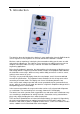
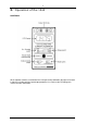
3. Operation of the 1044 CONTROLS All the operator controls are located on the front panel with calibration adjustments located inside the unit along with the input/output protection fuse. Refer to the Fault Diagnosis section for more information. V1.
3.1. Preliminary Operation of the 1044 can be defined as four different procedures; voltage source, current source, voltage measure and current measure. For correct operation ensure that the battery low indicator is not showing in the display. The output will only be indicated when the polarity switch is in either ‘normal’ or ‘reverse’ positions, not in the ‘off’ position. Be certain to check the polarity settings before connecting the unit under test.
3.4. Measuring a voltage input To measure a voltage input select the V function and select the appropriate range. If the input is unknown then choose the highest range. Select the measure mode and ensure that the polarity switch is set to normal. The reading should now be displayed. If the display shows the digit 1 with a blank character then the unit has over-ranged and must be switched to the next highest range. 3.5.
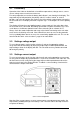
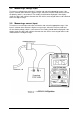
4. Operation of the 4-20mA S ys tem Introduction A common use of the 1044 would be to simulate a transducer or measure the current flow in a transducer loop. The following brief explanation, which is intended as a guideline only, may help when operating the 1044 in a 4-20mA system. The 4-20mA System The basic requirement for any transducer with remote display is: A) To use as few wires as possible.
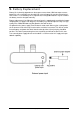
5. B attery R eplac ement Battery life is primarily dependent on the output currents drawn. With low output currents, battery life can exceed 50 hours, but with high currents battery life may be reduced to less than 5 hours. If a short battery life is experienced, rechargeable batteries may be used but the battery must be charged externally. Battery replacement is by sliding the rear panel up to its stopping point revealing the battery compartment (see page 12 for diagram).
6. R ec alibration Introduction Recalibration of the 1044 is essential to ensure both correct operation and maintain accuracy. Recalibration is recommended annually. This chapter gives calibration information. Recalibration This instrument is calibrated before it leaves the factory and the calibration controls will not normally need adjustment, although periodic annual re-calibration is recommended.
7. F ault Diagnos tic s Introduction This section gives details of some possible problems and how to correct them. Fault Check List If the 1044 is completely dead without any indication of the display working, check the following 1) Battery condition - replace battery. 2) Polarity of external power unit - reverse connections. The 1044 indicates an output but there is not an output at the terminals. 1) The output protection fuse has blown.
8. G uarantee & S ervic ing Guarantee Period. This unit is guaranteed against defects in materials and workmanship for a period of one year from its delivery to the customer. We maintain comprehensive after sales facilities and the unit can, if necessary be returned to us for servicing. During this period, Time Electronics Ltd will, at its discretion, repair or replace the defective items.
Time Electronics Calibrateur De Tension et de Courant 1044 Manuel Tec hnique (F ranc ais ) V1.
Table des Matieres 1. Introduction 16 2. Caracteristiques Techniques 17 3. Fonctionnement du 1044 19 4. Fonctionnement du Systeme de 4-20mA 23 5. Remplacement de la Pile 24 6. Re-Etalonnage 25 7. Diagnostic des Pannes 26 8.
1. Introduction Le 1044 a été conçu pour offrir des solutions dans de nombreuses applications allant du laboratoire de recherche et développement au technicien d'entretien, en fait n'importe où un calibrateur précis et peu onéreux est réclamé. Nous avons utilisé notre expérience en matière de conception d'instrumentation pour vous offrir le calibrateur le plus polyvalent et le plus pratique du moment.
2. Caracteristiques Techniques PLAGES Source de Tension Intensité Plage Résolution Précision de Sortie 0 - 200mV 100uV ± 0.05% 20mA 0 - 2V 1mV +±2 0 - 20V 10mV Chiffres Coefficient de Température par °C ± 150ppm Mesure de Tension Plage Résolution Précision Impédance d'entrée Coefficient de Température par °C 0 - 200mV 100uV ± 0.
BRUIT A LA SORTIE <30 ppm en tension maximale, <50 ppm en intensité maximale. CONNEXIONS Les connexions sont assurées par des connecteurs de type banane de 4mm ou peuvent être serrées à l'aide du système de compression des fils. PILES 1 batterie de type PP3, 6AM6, MN1604 ou 6LR61. La durée de vie de la pile est d'environ 30 heures, selon l'intensité générée.
3. Fonctionnement du 1044 COMMANDES Toutes les commandes de l'opérateur sont situées sur le panneau avant et les réglages d'étalonnage sont situés à l'intérieur de l'unité, ainsi que le fusible de protection d'entrée/sortie. Voir la rubrique Diagnostic des Pannes pour de plus amples informations. V1.
PRELIMINAIRE Le fonctionnement du 1044 peut être défini comme quatre procédures différentes: génération de tension, génération d'intensité, mesure de tension et mesure d'intensité. Pour le fonctionnement correct, s'assurer que l'indicateur de pile faible ne s'affiche pas. La sortie va seulement être indiquée lorsque le commutateur de polarité est soit en position "normale" (norm) soit en position "inverse" (rev), pas en position "off" (hors tension).
REGLAGE D'UNE SORTIE EN COURANT Pour définir une sortie en courant, régler le commutateur de fonction sur mA et sélectionner la plage d'intensité appropriée en s'assurant que le potentiomètre d'ajustage de sortie est réglé sur zéro. Brancher l'unité essayée. L'intensité désirée peut être réglée en tournant le potentiomètre multitour; l'intensité de sortie indiquée sur l'affichage va changer. Pour obtenir une mesure d'intensité, une charge doit être connectée à la sortie du 1044.
MESURE D'UNE ENTREE EN TENSION Pour mesurer une entrée en tension, sélectionner la fonction V et sélectionner la plage appropriée. Si l'entrée est inconnue, choisir la plage la plus élevée. Sélectionner le mode mesure et s'assurer que le commutateur de polarité est réglé sur normale. La mesure devrait désormais être affichée. Si l'affichage indique le chiffre 1 avec un blanc, l'unité a effectué un dépassement de calibre et la plage la plus élevée suivante doit être sélectionnée.
4. Fonctionnement du Systeme de 4-20mA INTRODUCTION Le 1044 est fréquemment utilisé pour simuler un transducteur ou mesurer la circulation du courant dans une boucle de transducteur. La brève explication suivante, présentée uniquement à titre indicatif, peut faciliter l'utilisation du 1044 dans un système de 4-20mA. LE SYSTEME DE 4-20mA Les exigences de base pour n'importe quel transducteur à affichage à distance sont les suivantes: a) Utiliser le moins de fils possible.
5. Remplacement de la Pile La durée de vie de la pile dépend principalement des courants de sortie absorbés. Avec des sorties à courant faible, la durée de vie de la pile peut dépasser 50 heures, mais avec des sorties à courant fort, la durée de vie de la pile peut être réduite jusqu'à moins de 5 heures. En cas de courte durée de vie de pile, il est possible d'utiliser des piles rechargeables mais la pile doit être chargée hors de l'instrument.
6. Re-etalonnage INTRODUCTION Le ré-étalonnage du 1044 est essentiel pour assurer un fonctionnement correct et maintenir la précision de l'instrument. Un ré-étalonnage annuel est recommandé. Ce chapitre présente des informations sur le ré-étalonnage. RE-ETALONNAGE Cet instrument est étalonné avant de quitter l'usine et les commandes d'étalonnage ne nécessitent généralement pas d'ajustage, mais un ré-étalonnage annuel est recommandé.
7. Diagnostic des Pannes INTRODUCTION Ce chapitre décrit certains problèmes possibles et la façon dont les corriger. LISTE DE CONTROLE DES PANNES Si le 1044 est sans aucune tension et qu'il n'existe aucune indication de fonctionnement de l'affichage, vérifier les points suivants: 1) Etat de la pile - remplacer la pile. 2) Polarité de l'entrée d'alimentation externe - inverser les connexions. Le 1044 indique une sortie mais il n'y a pas de sortie au niveau des bornes.
8. Periode de Garantie Cet instrument est garanti contre tout défaut de matériau et de fabrication pendant une période d'un an à dater de sa livraison au client. Nous assurons un service après-vente complet et, si nécessaire, l'unité peut nous être retournée pour entretien. Au cours de cette période, Time Electronics Ltd réparera ou remplacera l'article défectueux, à sa discrétion.
Time Electronics 1044 SPANNUNGS - UND STROMKALIBRATOR Tec hnis c hes Handbuc h (Deuts c h) V1.
Inhalt 1. Einfuehrung 30 2. Spezifikation 31 3. Betrieb der 1044 33 4. Betrieb des 4 – 20mA-Systems 36 5. Batterietausch 37 6. Rekalibrierung 38 7. Fehlerdiagnose 39 8. Garantie 40 Alle Time Electronics' instrumente unterliegen einer staendigen Entwicklung und Verbesserung und deswegen in Konsequenz, kann es kleinere Abweichungen vom technischen Handbuch geben. V1.
1. Einfuehrung Die 1044 wurde fuer den Entwicklungsingeneur fuer vielfaeltige Anwendungen entwickelt, ueberall dort, wo ein genauer und kostenguenstiger Kalibrator gebraucht wird. Wir haben unsere gesamte Erfahrung eingebracht, um ein moeglichst vielseitiges und praktisches Geraet anzubieten. Die 1044 kann sowohl als Spannungs- und Stromquelle und zusaetzlich als Messgeraet mit einer Genauigkeit von 0.
2. Spezifikation BEREICHE Spannungsquelle Bereich Aufloesung Genauigkeit 0 - 200mV 100uV ± 0.05% 0 - 2V 1mV + ± 2 Count 0 - 20V 10mV O/P Stromt T/C per °C 20mA ± 150ppm Spannungsmessung Bereich Aufloesung Genauigkei t Eingangs T/C per °C Impedanz 0 - 200mV 100uV ± 0.05% <2V = 1MΩ 0 - 2V 1mV +±2 0 - 20V 10mV Count <20V = 10MΩ ± 150ppm Stromquelle Bereich Aufloesung Genauigkeit O/P T/C per °C Spannung 0 - 200uA 100nA 0 - 2mA 1uA 0 - 20mA 10uA ± 0.
AUSGANGSRAUSCHEN <30 ppm von Vollausschlag bei Spannung, <50 ppm von Vollausschlag bei Strom. VERBINDUNGEN Verbindungen werden mit 4 mm Bananensteckern oder durch Klemmen unter die Buchsen hergestellt. BATTERIEN 1 Batterie Typ PP3 oder 6AM6 oder MN1604 oder 6LR61 Die Batterielebensdauer betraegt ca 30 Stunden, abhaengig vom gezogenen Strom. Alternativ kann ein 12V-Netzteil in die 3.5 mm Buchse am Kopfende eingesteckt werden, plus auf dem Pin.
3. Betrieb der 1044 KONTROLLE Alle fuer den Betrieb notwendigen Kontrollen sind auf der Frontplatte angebracht, die Kalibrierungspotentiometer sind jedoch innen neben der Sicherung. Im Fehlerdiagnostiksektor gibt es weitere Hinweise. VORLAEUFIGES Der Betrieb der 1044 kann fuer 4 Prozeduren definiert werden: Spannungsquelle, Stromquelle, Spannungsmessung und Strommessung. Fuer korrekten Betrieb sollte auf dem Display die Batterie keine Entladung anzeigen.
EINSTELLEN EINES AUSGANGSSTROMS Um einen Ausgangsstrom einzustellen, muss der Funktionsschalter auf mA gestellt und ein angemessener Bereich ausgewaehlt und mit dem Potentiometer der Strom auf Null gesetzt werden.Verbinde die zu testende Einheit.Danach kann der gewuenschte Strom durch das Potentiometer eingestellt und auf dem Display beobachtet werden.Um eine Stromanzeige zu erhalten, muss eine Last zugeschaltet sein.
MESSUNG EINER EINGANGSSPANNUNG Um eine Eingangsspannung zu messen , waehle die V- Funktion und einen erwarteten Bereich.Falls die Spannung gaenzlich unbekannt ist , waehle auf jeden Fall den hoechsten Bereich.Waehle den Messmodus und versichere Dich , dass der Polaritaetsschalter auf ‘Normal’ steht.Nach Herstellung der Verbindung wird die Spannung angezeigt.Zeigt das Display eine 1 und einem Leerzeichen , dann besteht Overflow und der naechst hoehere Bereich muss gewaehlt werden.
4. Betrieb Als 4 - 20mA – System EINFUEHRUNG Eine allgemeine Anwendung ist die Simulation eines Uebertragers oder die Messung eines Stroms in einer Uebertragungsschleife. Die folgende kurze Erklaerung, die nur als Anregung dienen soll, moege dabei helfen die 1044 in einem 4 – 20mA-System zu benutzen. DAS 4 – 20mA-SYSTEM Die Grundlegende Forderung fuer jeden Uebertrager mit einem externen Display ist: a) Benutze so wenig Verbindungen wie moeglich.
5. Batterieaustausch Die Lebensdauer der Batterie haengt vom gezogenen Strom ab.Mit kleinen Ausgangsstroemen kann die Lebensdauer groesser als 50 std sein, aber mit grossen Stroemen kann sie durchaus auf 5 std limitiert sein.Bei kurzen Lebensdauern werden wiederladbare Batterein von Vorteil sein.Das Geraet kann von extern geladen werden. Auf der Rueckseite des Geraets kann das Batteriefach geoeffnet werden.Danach kann die Batterie austauscht werden.
6. Rekalibrierung EINFUEHRUNG Die Rekalibrierung der 1044 ist wichtig , um beides -korrekten Betrieb und Messgenaigkeitzu erhalten.Es wird empfohlen die Einheit jaehrlich zu rekalibrieren. Dieses Kapitel gibt Informationen zur Kalibrierung. REKALIBRIERUNG Das Geraet verlaesst kalibriert die Fabrik und normalerweise benoetigt das Geraet keine Ueberpruefung der Kalibrierung, dennoch empfehlen wir eine jaehrliche Rekali-Bierung.
7. Fehlerdiagnose EINFUEHRUNG Dieses Kapitel beschaeftigt sich im Detail mit moeglichen Problemen und wie man sie korrigieren kann. FEHLERDIAGNOSELISTE Falls die 1044 total tot ist , ohne jegliche Anzeige , dann ueberpruefe das Folgende: 1) Batteriezustand-Ersetze die Batterie. 2) Polaritaet des externen Netzteils – tausche die Polaritaet. Die 1044 zeigt einen Ausgang auf dem Display, aber es ist kein Signal auf den Buchsen. Die Ausgangsschutzsicherung ist defekt.
8. Garantie GARANTIEPERIODE Dieses Instrument unterliegt einer Garantiezeit von einem Jahr, gerechnet ab Auslieferung zum Kunden.Die Garantie gilt fuer Material- und Fertigungsmaengel. Wir unternehmen einige After-Sales –Anstrengungen und die Einheit kann falls notwendig ins Werk zurueckgeschickt werden.Waehrend dieser Zeit ersetzt oder repariert Time Electronics Ltd defekte Bauteile.