Time Electronics 1030 MicroCal Voltage & Current Source. Technical Manual V3.2 01/11/10 Time Electronics Ltd Botany Industrial Estate, Tonbridge, Kent, TN9 1RH Tel: +44(0)1732 355993 Fax: +44(0)1732 770312 Email: mail@TimeElectronics.co.uk Web Site: www.TimeElectronics.
C ontents 1. Introduc tion ................................................................................................3 1.1. 2. S pec ific ations .............................................................................................4 2.1. 3. 4. 5. General Description................................................................................... 3 Ordering Information and Optional Extras............................................... 5 C ontrols ...................................
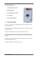
1. Introduc tion • 3 Voltage Ranges up to 1 Volt • Extremely Compact • 2 Current Ranges up to 100 mA • 0.1% Accuracy • Uses a single PP3 Battery 1.1. General Description The 1030 is a compact, low cost, portable voltage and current calibrator for general purpose signal injection. Three voltage ranges give adjustable output from 10uV to 1V, and two current ranges give 10uA to 100mA. The output is scaled directly and is varied by a high quality 10 turn dial.
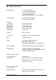
2. S pec ific ations Voltage Ranges: 0 - 1V (1mV resolution). 0 - 100 mV (100µV resolution). 0 - 10 mV (10µV resolution). 8 Volts (10mV resolution) using external precision 1KΩ resistor supplied. Current Ranges: 0 - 100mA (100µA resolution), 0 - 10mA (10µA resolution). Accuracy: 1 Volt range: 100mV range: 10mV range: 100mA range: 10mA range: 8 Volt range: ± 0.1% of FS ± 30µV. ± 0.1% of FS ± 3µV. ± 0.2% of FS ± 0.3µV. ± 0.2% of FS ± 3µA. ± 0.2% of FS ± 0.3µA. ± 0.3% of FS. Linearity: 0.
Output Resistance: 0.2 ohm on 1V and 100mV ranges. 10 ohm on 10mV range. 1K ohm when using the current shunt resistor. Dimensions: 115mm x 62mm x 55mm. Carry Case: A black carry case is supplied. 2.1.
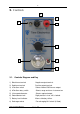
3. C ontrols 8 1 3 2 4 5 7 6 3.1. Controls Diagram and Key 1) Black 4mm terminal Negative output terminal. 2) Red 4mm terminal Positive output terminal. 3) 3 Position switch Selects Normal/Off/Reverse output 4) 6 Position rotary switch Selects range and turns instrument on 5) 10 turn potentiometer Selects required output 6) Potentiometer lock Right position is free, left is locked.
3.2. Description of Controls 1 / 2. Output Terminals Output Voltage and Current is available on two front panel terminals which are suitable for either wire compression or 4mm 'wander' plug insertion. 3. Polarity Switch Normal or reverse polarity is selected by a toggle switch. The centre position is OFF which provides an open circuit on the output terminals. 4.
4. Operation 4.1. Voltage Ranges Suggested operation procedure is as follows: Select Off position on output switch. Turn on, and select required range. Check battery level indicator for high enough reading (see ‘Battery Replacement’). Select required output on the ten turn potentiometer, which can then be locked by pushing the lever at the bottom to the left. The ten turn potentiometer linearly adjusts the output from zero to full scale on any range.
4.3. Current Ranges On the current ranges, the drive voltage available at the terminals is governed by the battery voltage. Care should be taken not to exceed the 1030 voltage limit, as large errors will result if the load/current product exceeds the 1030 8V drive capability. This can easily be checked by either measuring the voltage across the 1030’s terminals when under load, or by checking that R x I is less than 8 volts. 4.4.
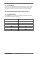
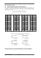
5. A pplic ations 5.1. Four Terminal Resistance Measurements Accurate measurements of low ohm values, such as P.R.T, can be performed by using the 1030 as a current source and measuring the voltage across the LOAD with a DVM. From Ohms Law : V/I=R Resistance vs Temperature Relationship for Platinum Resistance Thermometer Detector Element (DIN 43760) °C -200 -180 -160 -140 -120 -100 -80 -60 -40 -20 0 20 40 Ω 18.48 27.08 35.53 43.87 52.11 60.25 68.33 76.33 84.27 92.16 100.00 107.79 115.
5.2 Thermocouple Simulation The 10mV range of the 1030 is ideal for simulation of all types of thermocouple. Just find the voltage required from the British Standard tables, (common values given below), and set up on the 1030’s dial. Do not forget to allow for the Cold Junction temperature. Thermocouples Temperature tables ITS90. 100°C -50°C -25°C 0°C 25°C 37°C 50°C 75°C 100°C mV mV mV mV mV mV mV mV mV NiCr/NiAl Cu/Con Fe/Con Pt13%RH/Pt Pt30%RH / Pt6%RH Pt10%RH/Pt NiCr/NiSi -3.
6. B attery R eplac ement & R ec harging The battery capacity for rechargeable types is approx. 110mAH, whereas nonrechargeable types are approx. 70mAH. The 1030 circuitry takes 2mA, and will operate over a battery voltage range of 7-12 volts. The battery life is primarily dependent on the output current used. With low output currents, battery life can exceed 60 hours, but when driving a 100mA output current, battery life is reduced to about 50 minutes.
7. C alibration The instrument is calibrated before it leaves the factory and the calibration controls will not normally require adjustment. If re-adjustment is considered necessary, and the trimmer range is found to be insufficient for recalibration, there is a fault with the instrument. To calibrate the instrument a DVM of 0.1% accuracy is required.
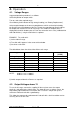
7.2. Module and Trimmer Location Fig. 2 11 Turn the output adjustment pot. to full scale, and adjust the full scale calibration trimmer until the DVM reads 100mV. The full scale for the instrument is then set up correctly. The other ranges do not normally require calibration, and therefore are not fitted with trimmers. Should calibration become necessary, adjust or replace the resistors listed below. 12 10mV F.S. R6 10mA F.S. R9 100mA F.S. R5 The instrument can now be reassembled.
8. Maintenanc e and R epair. 8.1. Dismantling the Instrument Remove rubber protection boot and then removal of four 6BA screws enables the cover to be taken off which provides access to all parts of the instrument. 8.2. Battery Replacement.
9. G uarantee & S ervic ing Guarantee Period This unit is guaranteed against defects in materials and workmanship for a period of one year from its delivery to the customer. We maintain comprehensive after sales facilities and the unit can, if necessary be returned to us for servicing. During this period, Time Electronics Ltd will, at its discretion, repair or replace the defective items.