Time Electronics 1024 DC Current Calibrator With Null Measuring Facility Technical Manual V1.1 20/04/09 Time Electronics Ltd Botany Industrial Estate, Tonbridge, Kent, TN9 1RH Tel: +44(0)1732 355993 Fax: +44(0)1732 770312 Email: mail@TimeElectronics.co.uk Web Site: www.TimeElectronics.
C ontents 1. 2. Introduction ............................................................................................................ 3 1.1. General Description................................................................................................ 3 1.2. Specifications ......................................................................................................... 4 Operation ......................................................................................................
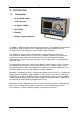
1. Introduction 1.1. Description • Up to 100mA output • 0.02% accuracy • 10 ppm/hr stability • Null facility • Portable • Battery & mains operation The 1024 is a solid state battery powered instrument which is easily portable and convenient for laboratory, field, or industrial use. It incorporates many of the well-proven circuit techniques of the Time Electronics Type 1010 DC Voltage Calibrator.
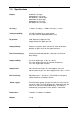
1.2. Specifications Output: 0-100mA in 5 ranges 0-99.999mA in 1uA steps 0-9.9999mA in 100uA steps 0-999.99uA in 10nA steps 0-99.999uA in 1nA steps 0-9.9999uA in 0.1nA steps Accuracy: +/- 0.02% of setting, +/- 0.005% of range, +/- 0.2nA Voltage Capability: 15V with new batteries or mains power (11V with minimum allowable battery level) Regulation: Load: Better than 5ppm per Volt Supply: Better than 5ppm per Volt Output polarity: Positive or negative switch selected.
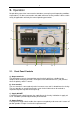
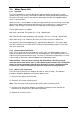
2. Operation Despite being a precision instrument the 1024 does not require special operating conditions or procedures. Its robust construction and stable solid state circuitry enables it to be used in nearly all applications with only the normal operating precautions. k i f g j h e b a d c 2.1. Front Panel Controls a) Output terminals The 1024 output current is from two front panel terminals which are suitable for wire compression or 4mm plug insertion.
e) Battery Level The battery (or mains power supply PU2) output is continuously monitored on a front panel indicator which also serves as a supply ‘on-off’ indication. A minimum mark indicates when the batteries need recharging. f) Range One of the five output ranges can be selected. g) Digit Switches A 5-decade thumbwheel switch enables the output current level to be set with a resolution of 0.01% of full scale. h) Voltage Limit An L.E.D.
2.2. Operating Procedures and Precautions 2.2.1. Normal Operation Operation of the 1024 is self-explanatory from the front panel controls and specifications. It is important to understand the 1024’s voltage capability and voltage limit indicator to ensure that your requirement is within the limit. It is also important to read section the section on output noise if your requirement is for current levels of less than a few tens of microamps.
It is important when confronted with a problem of noise pick-up to stop and think logically about the cause and effect - a good deal of time can be wasted by indiscriminate screening and earthing! This is particularly important when dealing with current signals since many of the effects are the exact opposite from those for voltage signals e.g. earthing one side of a voltage signal may reduce the noise pick-up but earthing the same side of a current signal may increase the pick-up.
2.4. Mains Power Unit 2.4.1. Type PU2 The PU2 incorporates a rechargeable Nickel-Cadmium battery and electronics charge control circuitry. The circuitry is arranged to enable the PU2 to provide power directly from the mains if the mains input is connected or alternatively from the rechargeable battery if mains is not connected.
3. Constructional Layout Details The complete instrument assembly (except the Power Unit) is mounted on the front panel. A printed circuit board which carries the components and range switch is located immediately behind the front panel. The panel and p.c.b. can be removed as follows: 1) Remove Power Unit - located in instrument rear by 4 screws. 2) Disconnect supply - connected to power unit by 2 press stud connectors. 3) Remove front panel locating screws. 4) Withdraw front panel and p.c.b.
4. Recalibration 4.1. Repairs Access to the circuitry is by removing the front panel which is located by 4 screws. Two preset trimmers are provided. One provides adjustment of the zero and the other full scale. If readjustment is necessary the output should be set up against suitable standards. Due to the precision nature of many of the components used in the 1024, they are not readily available to enable the customer to undertake repairs. Repairs to the power unit (Section 2.
b) The 1024’s output can be converted to voltage by using precision resistors on the 1024 output. High performance resistors are required with accuracies of better than 0.01%, 1ohm, 10 ohms, 100 ohms, 1K ohm and 10K ohms are usually adequate. The low values must have excellent stability at currents up to 100mA if errors are not to be introduced due to the temperature rise in the resistor under load. Power dissipation is 1 watt in the 10 ohm at 100 mA.
5. Guarantee & Servicing Guarantee Period This unit is guaranteed against defects in materials and workmanship for a period of one year from its delivery to the customer. We maintain comprehensive after sales facilities and the unit can, if necessary be returned to us for servicing. During this period, Time Electronics Ltd will, at its discretion, repair or replace the defective items.