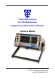
Time Electronics 1017 DC Multifunction Voltage/Current/Resistance Calibrator Technical Manual V1.2 01/11/10 Time Electronics Ltd Botany Industrial Estate, Tonbridge, Kent, TN9 1RH Tel: +44(0)1732 355993 Fax: +44(0)1732 770312 Email: mail@TimeElectronics.co.uk Web Site: www.TimeElectronics.
C ontents 1. Introduc tion ............................................................................................................ 3 1.1. General Description................................................................................................ 3 1.2. Specifications ......................................................................................................... 4 1.3. Circuit Description..........................................................................................
1. Introduction 1.1. General Description The 1017 is a high performance portable calibrator for use in the field or laboratory. With voltage ranges from 10nV to 100V, current from 100nA to 100mA and resistance from 10mΩ to 10kΩ, it makes the 1017 an extremely versatile instrument, capable of calibration or simulation. The digital deviation control allows the output to either increase or decrease directly in a percentage from 0.001% to 0.999%.
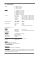
1.2. Specifications Outputs: Voltage Range: 0 – 100V in 5 Ranges 0 – 100mA in 1 Range 0 – 10kΩ in 1 Range 0 – 9.99999mV in 10nV steps 0 – 99.9999mV in 100nV steps 0 – 999.999mV in 1uV steps 0 – 9.99999V in 10uV steps 0 – 99.9999V in 100uV steps Accuracy: 10mV range 100mV range 1V range 10V range 100V range 0.02% of setting +/- 0.005% of range 0.01% of setting +/- 0.004% of range 0.005% of setting +/- 0.002% of range 0.005% of setting +/- 0.002% of range 0.01% of setting +/- 0.
Dimensions & Weight Dimensions – 290mm x 250mm x 110mm Weight – 2.4Kg Operating Temperature 0°C to +50°C max. For optimum performance and stability the 1017 should be stored and used in temperatures between 15°C and 25°C. 1.3. Circuit Description The calibrator employs a temperature compensated zener diode as the basic reference source.
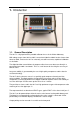
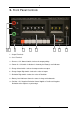
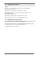
2. Front Panel Controls 1 2 3 4 5 6 7 8 1 – Output Terminals. 2 – Case Terminal. 3 – Reverse / Off / Normal Switch, Selects the output polarity. 4 – Power On / Off Switch. Indication is shown by the Battery Level Indicator. 5 – Range Select Switch. Selects the output maximum output. 6 – Range Output Digit Switch. Selects the value of output. 7 – Deviation Digit Switch. Selects the value of Deviation. 8 – Battery Level Indicator. Shows the state of charge of the batteries.
3. Operation 3.1. Preparing for Use Before using the 1017, you must first check to see if the battery level indicator shows that the batteries are in a good state of charge. If the indicator shows that they are low then you must recharge them by plugging the 1017 into the mains supply. It will take approximately 12 – 14 hours to fully recharge the battery pack. You may of course use the 1017 when it is plugged into the mains supply irrespective of the battery state.
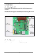
4. Calibration 4.1. Calibrating the 1017 The 1017 can be calibrated with a high accuracy D.M.M. with D.C. voltage, current and resistance ranges with a specification of at least 4 times greater than that of the 1017’s specifications. Calibration is best carried out on fully charged batteries without the mains supply connected to ensure that no mains supply interference takes any effect on the readings. 4.2.
4.3. Calibrating the Full Scales After checking the zero settings you may then calibrate the full scales. Set the digit switch to ’999999’. Adjust the 1V Full Scale with the ’CAL’ trimmer which is on the potted module. Adjust this to read 1V to within 20uV. Adjust the 10V F.S. trimmer, VR5, to read 10V to within +/- 200uV. Adjust the 100mV & 10mV F.S. trimmer VR3, to read 100mV to within +/ - 4.3µV (Done on 100mV Range) Check 10mV F.S. is within 1.3µV. Adjust the 100V F.S.
5. Guarantee & Servicing Guarantee Period This unit is guaranteed against defects in materials and workmanship for a period of one year from its delivery to the customer. We maintain comprehensive after sales facilities and the unit can, if necessary be returned to us for servicing. During this period, Time Electronics Ltd will, at its discretion, repair or replace the defective items.