Time Electronics 1006 DC Millivolt Source and 1007 DC Millivolt Potentiometer & Source Technical Manual Version 1.1 20/04/09 Time Electronics Ltd Botany Industrial Estate, Tonbridge, Kent, TN9 1RH Tel: +44(0)1732 355993 Fax: +44(0)1732 770312 Email: mail@TimeElectronics.co.uk Web Site: www.TimeElectronics.
C ontents 1. General Descriptions ......................................................................................... 3 1.1. 1006 DC Millivolt Source .................................................................................... 3 1.2. 1007 Millivolt Potentiometer and Source .......................................................... 4 2. Specifications ..................................................................................................... 5 3. Operating Instructions ....
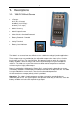
1. Descriptions 1.1. 1006 DC Millivolt Source • 3 Ranges 0-1V (0.1 mV steps) 0-100mV (10 uV steps) 0-10mV (1 uV steps) • 0.02% Accuracy • 20mA Output Current • Short Circuit & Overload Protected • Battery Powered – Portable • Safety Terminals • Battery Level Indicator The 1006 is an accurate low cost millivolt source suitable for voltage injection applications. Three output ranges are provided to give adjustable output values from 1µV to 1V with a basic 0.02% accuracy.
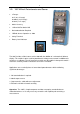
1.2. 1007 Millivolt Potentiometer and Source • 3 Ranges 0-1V (0.1 mV steps) 0-100mV (10 uV steps) 0-10mV (1 uV steps) • 0.02% Accuracy • 1 Micro-Volt Resolution Null • No Standardisation Required • Millivolt Source Operation as 1006 • Safety Terminals • Battery Level Indicator The 1007 includes all the features of the 1006 with the addition of a microvolt null balance display. This enables it to be used for potentiometric voltage measurement in addition to its function as a calibrator.
2. Specifications Output: 0.999.9mV in 3 ranges 0.999.9mV in 0.1mV steps 0.99.99mV in 10uV steps 0.0.999mV in 1uV steps Accuracy: ± 0.02% of setting ± 0.02% of range Output Resistance: Less than 0.1 ohm on 1V and 100mV ranges. 1 ohm on 10 mV range. Maximum Output Current: 1V and 100mV ranges - 20mA. 10mV range: Up to short circuit value although it should be noted that loads of less than 1K ohm will give greater than 0.1% error. Output Voltage Stability: Less than 60ppm/°C.
3. Operating Instructions The 1007 incorporates a 1006 with the addition of a microvolt null detector and enables the unit to be used for potentiometric measurements. The additional front panel components are: 1) Null Balance Meter 2) Null Zero Adjust Control 3) Null Sensitivity Adjust Control 4) Function Switch marked SOURCE:POTENTIOMETER:ZERO 3.1. Battery Insertion To insert batteries, remove two black covers on top of the instrument by pressing in and turning 90° anti-clockwise.
3.4. Internal Preset Controls IMPORTANT NOTE: These controls are set in the factory before shipment and normally will not require readjustment. If readjustment is considered necessary, it is important to check that the amount of adjustment required is within the range of the trimmer concerned. If it is greater than the trimmer range, there is no point in attempting to readjust and a fault condition will exist in the unit. The range of adjustment of the trimmers is given below.
Calibration Procedure 1) Check zero output is correct as described on Page 6. 2) Select 999.9 mV range and ‘normal’ output polarity. 3) Set output digits to 9999. 4) Connect the accurate voltage source and microvolt null meter to the 1006 output in a potentiometric mode. 5) Set the voltage source to 999.9mV output and adjust the ‘1V CAL’ trimmer on the module to bring the 1006 output within specification. The maximum amount of adjustment available on this trimmer is 0.8%. 6) Select 99.
1007 Millivolt Source and Potentiometer The 1007 incorporates a 1006 with the addition of a microvolt null detector. With the front panel function switch in the ‘SOURCE’ position, the unit operates as a 1006 and the ZERO and CALIBRATION setting procedures are identical to those for the 1006. The potentiometer position of the function switch connects a high performance null balance system in series with the output. The null zero and sensitivity are adjustable by front panel controls. Maximum sens.
4. Guarantee & Servicing Guarantee Period This unit is guaranteed against defects in materials and workmanship for a period of one year from its delivery to the customer. We maintain comprehensive after sales facilities and the unit can, if necessary be returned to us for servicing. During this period, Time Electronics Ltd will, at its discretion, repair or replace the defective items.