
User's Manual

TigoMaster 2TH User Manual
Page 18 of 36
CONFIDENTIAL
Copyright © 2020 CoreTigo Ltd.
- Ensure that the requirements of the device for vibration and shock resistance are met at the
installation site.
- Mount the device so that the diagnostic LEDs of the device remain visible.
- Observe the following instructions for the installation procedure:
- Disconnect the system from the power supply before you start installation.
- Ensure sufficient equipotential bonding in your system.
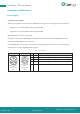
- During installation, make sure that you do not soil the connections. Dirt will damage the contacts,
resulting in
Notes on protection against the heat generated by the device
The device can become hot during operation! Therefore, always observe the following instructions:
- The cooling of the unit must not be impaired.
- Ensure an unobstructed air supply!
- Do not install the unit near strong heat sources!
- Do not mount the unit on or near highly inflammable materials.
Mounting of the device
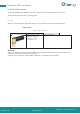
You can attach the device directly to your system or in the control cabinet with screws. Fasten the device
to a flat, solid base with two M4 screws, each of which is screwed into a threaded hole. Section Technical
data [} page 76] contains the specification of the tightening torque.
Note:
Note that the device requires a connection to FE (functional earth) via the screws.
The procedure for this is as follows:
- Hold the unit in the desired position and mark the two points where the threads are to be cut. Make
sure that there is enough space around the device so that you can connect all cables without any
problems.
- Cut an M4 thread at each of the two marked points with the M4 thread cutter, if necessary, pre-drill
with the drill first.
- Screw the unit into the threaded holes with the Allen key using two M4 cylinder head screws of
suitable length at the upper and lower ends. Observe the tightening torque.