
User's Manual

TigoMaster 2TH User Manual
Page 12 of 36
CONFIDENTIAL
Copyright © 2020 CoreTigo Ltd.
Connectors and interfaces
Power supply
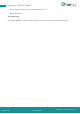
Connectors X21 and X22
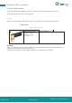
The device is supplied via connector X21 (PWR IN). You can connect two supply lines to the connector:
- Supply line 1: 1L (U1L) and the reference potential 1M
- Supply line 2: 2L (U2L) and the reference potential 2M
Both supply lines are electrically isolated.
Each pin of connector X21 (PWR IN) is connected to the same pin of socket X22 (PWR OUT) and is
used to forward the supply to the next device.
For identifying the connector X21 on the board, see position (20), and connector X22, see position (8) in
section Device overview TigoMaster 2TH- [page 6].
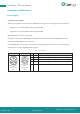
Table 5 - Power supply
PWR IN
PWR OUT
Pin
Signal
Description
M12, L-coded,
M12, L-coded,
female
5-pin (4 + FE)
X22
1
1L
+24 V DC power supply for system and sensor, U
1L
2
2M
Ground for 2L
3
1M
Ground for 1L
4
2L
+24 V DC power supply for auxiliary/switched power supply,
U
2L
FE
FE
Functional earth
male
5-pin (4 + FE)
X21