an spx brand TIFZX Heated Pentode™ Refrigerant Leak Detector Owner’s Manual Manual del propietario Manuel de l’utilisateur
table of contents General Description . . . . . . . . . . . . . . . . . . . . . . . . . . . . . . . . . . 2 Features . . . . . . . . . . . . . . . . . . . . . . . . . . . . . . . . . . . . . . . . . . . . 2 Parts & Controls . . . . . . . . . . . . . . . . . . . . . . . . . . . . . . . . . . . . . 3 Getting Started Unpacking . . . . . . . . . . . . . . . . . . . . . . . . .
general description Thank you for purchasing the TIFZX Heated Pentode™ Refrigerant Leak Detector. We are proud to offer what we believe is the very best portable electronic leak detector available today. TIFZX offers the greatest sensitivity and fastest response of any portable refrigerant detector available. This is achieved through the employment of a Heated Pentode™ sensor combined with a sophisticated microprocessor-controlled circuit.
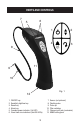
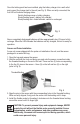
parts and controls 7 6 5 8 1 2 4 3 11 9 10 Fig. 1 12 1. On/Off key 2. Sensitivity high/low key 3. Reset key 4. Alarm key 5. Constant power indicator (1st LED) 6. Visual leak size indicators (2nd-6th LEDs) 3 7. Sensor (not pictured) 8. Flexible probe 9. Probe tip 10. Filter cartridge 11. Charger input jack (underside) 12.
getting started WARNING: To prevent personal injury, do not use this Leak Detector in an explosive or combustible atmosphere. Ambient atmosphere is drawn through the probe and sensor, which operate at a very high temperature. The resulting hot mixture of air and combustible gas could explode. Unpacking Unpack the unit from the carton and carrying pouch. Refer to the Parts and Controls section for parts identification.
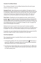
Once the battery pack has been installed, plug the battery charger into a wall outlet and connect the charger jack to the unit (see Fig. 3). When correctly connected, the first LED will indicate charging status: Quickly flashing orange = battery charging Slowly flashing green = battery fully charged Slowly flashing red = failed batteries; cannot be recharged Fig. 3 New or completely discharged batteries will take approximately two (2) hours to fully recharge.
operating features This unit includes operating features designed to increase usability and simplify user interface. Please refer to the Parts and Controls diagram on page 3 to familiarize yourself with the indicators and keypad controls as you proceed through this section. Constant Power Indication The Constant Power indicator allows the user to see the battery level at all times.
Automatic Circuit/Reset Feature The unit features Automatic Circuit and Reset functions that set the unit to ignore ambient concentrations of refrigerant. Automatic Circuit - Upon initial power-on and completion of the warm-up, the unit automatically sets itself to ignore the level of refrigerant present at the tip. Only a level, or concentration, greater than this level will cause an alarm.
The standard beeping tone is also an indication of sensitivity level. - In High sensitivity the unit emits two quick beeps approximately once every two (2) seconds, in fresh air. - In Low sensitivity the unit emits only one beep, approximately once every two (2) seconds, in fresh air. Sensor Status Indicator The unit’s circuit has the ability to automatically diagnose and indicate the sensor’s status.
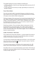
Constant Power Indicator (1st LED) Proportional indicators (2nd – 6th LEDs) Figure 5 When a refrigerant is detected, the visual indicator lights from left to right; first in green, then sequentially in orange, and then sequentially in red. Often, on anything but the smallest leak, the extreme sensitivity of the unit may cause the LEDs to all light in orange or red. Since each LED can appear in one of three colors – green, orange or red – this will result in 15 distinct alarm levels.
5. Begin searching for leaks. Move the probe tip toward the suspected leak. The flexible probe may be shaped to provide access to hard-to-reach areas. NOTE: If the unit has previously been in service, verify the probe tip is not obstructed with dirt, grease, etc., and check the condition of the filter as described in the Maintenance section. 6. If a refrigerant is detected, the unit will begin to alarm – the audible tone will quicken and the LEDs will light.
4. In windy areas, even a large leak can be difficult to find. Under these conditions, it is best to shield the potential leak area from wind or breezes. 5. A leak is a constant source of refrigerant, and when a true leak source is located, it should produce a repeatable alarm each time it is approached. Intermittent (nonrepeatable) alarms are often caused by accumulations of refrigerant near or around leak points. 6.
6. Verify an apparent leak as follows: a) Blow shop air into the area of the suspected leak. Repeat the check of the area. In cases of very large leaks, blowing out the area with shop air often helps locate the exact position of the leak. b) Move the probe to fresh air and reset. Then hold the probe tip as close as possible to the indicated leak source, and slowly move around it until the leak is confirmed. Automotive A/C Systems Only 7.
2. When correctly connected, the first LED indicates the charging status: - Quickly flashing orange = battery charging - Slowly flashing green = battery fully charged - Slowly flashing red = batteries failed; cannot be recharged New or completely discharged batteries take approximately two (2) hours to fully recharge. 3. When the LED indicates the batteries are fully charged (slowly flashing green), the unit is ready for operation.
As described in the Operating Features section, the unit’s circuit automatically diagnoses and indicates the sensor’s status. If an Old Sensor Indication is received, obtain a new sensor as soon as possible. Refer to the Replacement Parts section . If a Failed (or missing) Sensor Indication is received: 1. Remove the flexible probe by firmly grasping it and rotating it counterclockwise. This exposes the sensor in the end of the unit (see Fig. 7). Verify the sensor is installed. A.
Threaded Bushing Fig. 8 Pins Sensor 6. Install the flexible probe by threading it clockwise onto the threaded brass bushing around the sensor until it is finger tight. CAUTION: To prevent personal injury and equipment damage, NEVER operate the unit without the flexible probe correctly installed. Sensor contamination, erratic performance, and other problems may occur. Additionally, the sensor will become quite hot during operation, which could be dangerous.
Filter Cartridge and Tip Installation Instructions 1. Remove existing tip and old filter. Replace existing o-rings, if damaged. 2. Verify probe is clean. Use dry shop air to blow out both ends of the probe, if possible. 3. Install new filter cartridge to the probe with pointed ends of the raised ribs oriented toward the tip. See Figure 9. 4. Thread the new tip onto the filter cartridge. The filter cartridge should be snug against both o-rings.
SPECIFICATIONS Sensor Technology: Heated PentodeTM (advanced heated diode) Electronic Technology: Microprocessor-controlled circuit, including constant battery and sensor condition detection Sensitivity: Per SAE J1627 criteria; 0.5 oz/yr (14 gr/yr) for R134a, R22, and R12 Ultimate Sensitivity: High sensitivity—less than 0.1 oz/year (3 gr/yr) R134a Low sensitivity—as low as 0.
REPLACEMENT PARTS Several components of the unit are consumable and will eventually require replacement. Additionally, optional accessories for the unit are available through your dealer. Specify the part number below to ensure obtaining the correct part.
WARRANTY This product has been produced to provide unlimited service. Should it become inoperable after the user has performed the recommended maintenance, a no-charge repair or replacement will be made to the original purchaser. This applies to all repairable units that have not been damaged or tampered with. The claim must be made within Three years of the date of purchase. The Battery Pack is covered under warranty for 90 days.
TROUBLESHOOTING Symptom Possible Cause Power indicator LED does not light. (Unit does not switch ON.) Batteries are not charged. Audible alarm does not sound even though LEDs light. MUTE feature is engaged. Constant Power Indicator flashes On and OFF. This is the Old Sensor Indication. All LEDs flash red, and pump Failed sensor. does not run. Unit behaves erratically alarms in fresh air. During battery charging, the charge indicator goes out after 10 minutes.
655 Eisenhower Drive Owatonna, MN 55060-0995 USA Toll free 800 327 5060 llamada gratuita 800 327 5060 appel gratuit 800 327 5060 Fax 866 287 7222 telécopieur 866 287 7222 www.tif.