TIF RX-1A and XL-1A Refrigerant Leak Detectors Ownerʼs Manual Manual del Propietario Guide de l'utilisateur Bedienungsanleitung
BOTH MODELS ARE: DESIGN CERTIFIED BY MET LABORATORIES, INC. TO MEET SAE J1627 FOR R134a, R12 AND R22. CLASS 1 DIVISION 2 GROUPS C & D HAZARDOUS LOCATIONS HAND HELD GAS DETECTOR CLASSIFIED BY UN DERWRITERS C US LABORATORIES, INC.® AS TO FIRE ELECTRICAL SHOCK AND EXPLOSION HAZARDS ONLY. READ OWNERS MANUAL BEFORE OPERATING. CAU TION: TO REDUCE THE RISK OF ELECTRIC SHOCK,DEENERGIZE UNIT BEFORE REPLACING SENSING TIP OR SERVICING UNIT, USE ONLY WITH 1.5V ALKALINE BATTERIES, SIZE C.
TABLE OF CONTENTS General Description ............................................................ 2 Features .............................................................................. 2 Parts & Controls .................................................................. 3 Getting Started..................................................................... 3 Installing Batteries ..................................................... 3 Operating Features....................................................
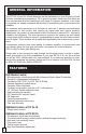
GENERAL INFORMATION The TIF RX-1A and XL-1A leak detectors are the culmination of over 30 years of Leak Detector manufacturing experience. TIF is proud to present these tools into which we have incorporated all of our experience, and years of customer feedback, in the hope of providing our valued customers with the best of everything; price, performance and reliability. An advanced micro-processor is at the heart of each unit.
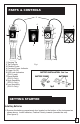
PARTS & CONTROLS 3 4 4 4 5 5 6 8 9 7 9 8 7 5 1 1 2 1 Sensing Tip 2 Tip Protector 3 Flexible Probe 4 Constant Power Indicator 5 Power On/Off 6 LED Leak Indicators (RX-1A only) 7 Reset Button (RX-1A Only) 8 High Sensitivity (RX-1A Only) 9 Low Sensitivity (RX-1A Only) 4 6 2 Fig.1 GETTING STARTED Installing Batteries 1. Remove the battery compartment door located on the bottom of the instrument as shown above. Install batteries, Positive Polarity inwards (towards the unit). (See figure 2).
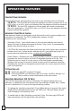
OPERATING FEATURES Constant Power Indication The Constant Power indicator allows the user to see the battery level at all times. TIF XL-1A - The Red LED will remain on whenever the unit is powered on. If the LED is dim, or is not lit, this is an indication that the batteries should be replaced. TIF RX-1A - The first LED (leftmost) in the bargraph will remain on whenever the unit is powered on. If the LED is dim, or is not lit, this is an indication that the batteries should be replaced.
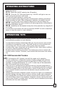
OPERATING INSTRUCTIONS 1. Switch the unit on XL-1A - Move the ON/OFF switch to the ON position. RX-1A - Press the "I/O" (Red and Green) key. All LED's will light for two seconds as the unit performs a self check. 2. The unit will begin beeping at a steady rate. 3. Verify the battery level by observing the constant power indicator (see above). 4. Begin searching for leaks. When refrigerant is detected, the audible tone will change to a 'siren' type sound, distinctly different from the base beep rate.
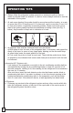
OPERATING TIPS 4. Always follow the refrigerant system around in a continuous path so that no areas of potential leaks are missed. If a leak is found, always continue to test the remainder of the system. 5. At each area checked, the probe should be moved around the location, at a rate no more than 25 to 50 mm/second (1-2 in/second), and no more than 5 mm (1/4 in) from the surface, completely around the position.
APPLICATIONS Both of the Leak Detectors covered by this manual may be used to: • Detect refrigerant gas leaks in Air Conditioning or Refrigeration systems and storage/recover containers. These detectors will respond to ALL halogenated (contains Chlorine or Fluorine) refrigerants. This includes, but is not limited to: CFCs e.g. R12,R11,R500,R503 etc... HCFCs e.g. R22,R123,R124,R502 etc... HFCs e.g. R134a, R404a, R125 etc... Blends such as AZ-50, HP62, MP39, R410a etc...
MAINTENANCE To replace the tip: 1. Make sure the unit is OFF. 2. Remove the old tip by unscrewing counter-clockwise. 3. Use the supplied replacement tip, located in the carrying case. Replace by screwing on clockwise. REPLACEMENT PARTS Standard Equipment Your Halogen Leak Detector comes equipped with one Carrying Case, one Owner's Manual, and one replacement Sensing Tip. To purchase replacement parts for you leak detector please contact your local TIF distributor.
SPECIFICATIONS Power Supply: Maximum Sensitivity: Ultimate sensitivity TIFXL-1A TIFRX-1A Sensing Tip Life: Operating Temperature: Battery Life: TIFXL-1: TIFRX-1A: Duty Cycle: Response Time: Reset Time: Warm-Up Time: Unit Weight: Unit Dimensions: Probe Cord Length: 3V DC; two “C" cell Alkaline batteries Per SAE J1627 Rating Criteria Certified @ 0.5 oz/yr. (14gr/yr) less than 0.4 oz/yr (11 gr/yr) for all Halogen based refrigerants. less than 0.
ESPAÑOL TIF XL-1A Y TIF RX-1A DETECTOR AUTOMATICO DE FUGAS DE HALOGENO Los detectores de fugas TIF RX-1A y XL-1A son la culminación de más de 30 años de experiencia en la fabricación de Detectores de Fugas. TIF se enorgullece de presentar estos instrumentos a los cuales se les ha incorporado toda nuestra experiencia, y años de comentarios y sugerencias de nuestros clientes, con la esperanza de proporcionar a nuestros valiosos clientes lo mejor de todo: precio, rendimiento y confiabilidad.
Características adicionales del TIF RX-1A • • • • • • Indicador visual de seis segmentos del tamaño de la fuga Una bomba mecánica proprociona flujo de aire positivo a través de la punta sensora Niveles altos y bajos de sensibilidad Restauración del equipo pulsando un botón Teclado de control Ajuste de sensibilidad de tiempo real Piezas y Controles 3 4 4 5 5 4 4 6 9 6 8 7 9 8 7 5 1 2 Fig.
Carácterística de restauración/circuito automático Ambos detectores poseen un circuito automático que ajusta la unidad para que ignore las concentraciones de refrigerante en el ambiente. El RX-1A tiene además una tecla de función de Restauración para comodidad. • Circuito automático – En el momento de la activación inicial, la unidad se ajusta automáticamente para ignorar el nivel de refrigerante presente en la punta. Sólo un nivel, o concentración, mayor que este dará lugar a una alarma.
RX-1A – La sensibilidad se puede ajustar en cualquier momento durante la operación mediant el uso de las teclas de HI o LO. 6. Si se produce una alarma total antes de localizar la fuga, RESTAURE la unidad como se describe con anterioridad, para restaurar el circuito a la referencia cero. 5. SUGERENCIAS DE OPERACION La sección siguiente incluye varias sugerencias generales de operación y el procedimiento recomendado por la SAE J1628 para la detección de fugas. 1.
b) Mueva primero la sonda hacia el aire libre y reajústela. Después, sostenga la punta de la sonda lo más cerca posible del punto de fuga indicado, y muévala lentamente alrededor del mismo hasta confirmar la fuga. Sistemas de A/C de Automóviles solamente 7.
3. Si la punta está sucia, se puede limpiar sumergiéndola en un disolvente suave, como el alcohol, durante unos segundos y después usando aire a presión y/o una toalla de taller para limpiarla. NOTA: Nunca use disolventes como gasolina, aguarrás, alcoholes minerales, etc... ya que dejarán un residuo detectable y desensibilizarán su unidad. Sustitución de la punta sensora: Con el tiempo, la punta se desgastará y deberá sustituirse.
GARANTIA Y REPARACION Este instrumento se ha diseñado y fabricado para proporcionar servicio ilimitado. Si la unidad no funciona después de realizarse el mantenimiento recomendado, se reparará o sustituirá sin costo adicional para el comprador original si la reclamación se hace dentro del plazo de dos años a partir de la fecha de compra. Esta garantía se aplica a todos los instrumentos reparables que no han sido forzados ni dañados por un uso inapropiado.
• • • • • • • • • Indicateur de tension de la pile Sans fil, fonctionne avec deux piles “C” Cordon flexible avec tige flexible de 35,5 cm en acier inoxydable Tete de détectioncomprise Répond aux normes UL Répond aux normes CE Mallette de transport comprise, etui de transport (en option) Guide de référence des sources de fuites (en option) Garantie de 2 ans Caractéristiques supplémentaires du TIF XL-1A • Interrupteur de commande unique Caractéristiques supplémentaires du TIF RX-1A • • • • • • Témoin vis
Instructions D'Installation De Batterie Retirez la porte de soute de batterie située sur le bas de l'instrument comme montré ci-dessous. Installez les batteries, polarité positive à lʼintérieur (vers lʼunité). (voir le schéma 2) . Témoin d’alimentation constante Le témoin dʼalimentation constante permet à lʼutilisateur de voir le niveau de la pile à tout instant. TIF XL-1A – La LED rouge restera allumée chaque fois que lʼappareil est en marche.
UTILISATION 1. Allumez lʼappareil XL-1A – Mettez lʼinterrupteur ON/OFF (MARCHE/ARRET) en position ON. RX-1A – Appuyez sur la touche « I/O » (Rouge et Vert). Toutes les LED sʼallumeront pendant deux secondes pendant que lʼappareil effectue des tests automatiques. 2. Lʼappareil commencera à bîper à une fréquence régulière. 3. Vérifiez le niveau de la pile en observant le témoin dʼalimentation constante (voir ci-dessus). 4. Commencez à chercher des fuites.
4. Suivez toujours le système de réfrigération en parcourant des routes continues afin quʼaucune zone pouvant présenter des fuites ne soit oubliée. Si vous trouvez une fuite, poursuivez toujours le test du reste du circuit. 5. Pour lʼinspection complète de chaque zone, la sonde devrait être déplacée autour de cette dernière à une vitesse ne dépassant pas 25 à 50mm/seconde (1-2 pouces/seconde) et à une distance de la surface ne dépassant pas 5mm (1/4 de pouce).
ENTRETIEN Un entretien suivi est essentiel pour votre Détecteur de Fuite. En suivant les instructions ci-dessous à la lettre, vous réduirez les problèmes dʼutilisation et prolongerez la vie utile de lʼappareil. ATTENTION: ETEIGNEZ LʼUNITE AVANT DE REMPLACER LA TETE DE DETECTION. LE NON-RESPECT DE CETTE PRECAUTION PEUT ENTRAINER UN LEGER CHOC ELECTRIQUE! La tête de détection doit rester propre: Evitez lʼaccumulation de poussière, dʼhumidité et de graisse en utilisant le protège-tête fourni.
DONNEES TECHNIQUES Alimentation: Sensibilité: Sensibilité maximum: XL-1A RX-1A Longevité de la tête de détection: 3Vdc; deux piles alcalines «C» Suivant critère dʼévaluation SAE J1627; Agréé pour R12, R22 et R134a @ 14gr/an Moins de 11 gr/an, Moins de 7 gr/an, pour tous les réfrigérants à base dʼhalogènes XL-1A 40 heures environ RX-1A 30 heures environ Température de fonctionnement: Durée de vie des piles: Facteur de marche: Temps de réponse: Temps de rem
DEUTSCH TIF XL-1A und TIF RX-1A AUTOMATISCHER HALOGEN-LECKDETEKTOR Die Leckdetektoren TIF RX-1A und XL-1A sind das Ergebnis von 30 Jahren Erfahrung in der Herstellung von Leckdetektoren. TIF ist stolz darauf, diese Geräte vorstellen zu können, denn in sie haben wir alle unsere Erfahrung und den jahrelangen Feedback unserer Kunden integriert, in der Hoffnung, unseren geschätzten Kunden das Beste hinsichtlich Preis, Leistung und Zuverlässigkeit zu bieten.
Geräteteile und Bedienelemente 3 4 4 4 6 5 5 4 6 8 9 7 9 8 7 5 1 1 2 1 Sondenspitze 2 Schutzkappe 3 Flexsonde 4 Betreibsschaler 5 Strom Ein/Aus 6 LED-Leckanzeigen (nur RX-1A) 7 Rücksetztaste (nur RX-1A) 8 Hohe Empfindlichkeit (nur RX-1A) 9 Niedrige Empfindlichkeit (nur RX-1A) 2 Fig. 1 Seitenansicht BATTERIEFACHVERSCHLUSS BATTERIEN Fig. 2 Installieren der Batterien Zum Einsetzen der Batterien den Verschluß des Batteriefachs unten am Gerät wie gezeigt herausschieben, und Batterien einlegen.
Automatische Schalttechnik – Wenn das Gerät zum ersten Mal eingeschaltet wird, stellt sich das Gerät automatisch so ein, daß es das an der Sensorspitze vorhandene Kühlmittelniveau ignoriert. Nur ein Niveau bzw. eine Konzentration, die dieses übersteigt, löst einen Alarm aus. VORSICHT: Dabei ist zu bedenken, daß aufgrund dieser Funktion das Gerät sämtliches Kühlmittel ignoriert, das beim Einschalten vorhanden ist.
BETRIEBSHINWEISE Der folgende Abschnitt enthält verschiedene allgemeine Betriebshinweise und das gemäß SAEJ1628 empfohlene Lecksuchverfahren. 1. In stark mit Gas kontaminierten Bereichen kann das Gerät zurückgesetzt werden, um die in der Umgebung befindlichen Gaskonzentrationen zu ignorieren. Die Sonde darf während des Rücksetzens nicht bewegt werden. Das Gerät kann beliebig oft rückgesetzt werden. 3. In windigen Bereichen lassen sich selbst große Lecks nur schwer feststellen.
Nur Autoklimaanlagen 7. Zum Lecktest des Verdampferkerns im Klimaanlagenmodul das Klimaanlagengebläse mindestens 15 Sekunden lang hochtourig laufen lassen, dann abschalten und 10 Minuten warten, damit sich das Kühlmittel im Gehäuse ansammeln kann. Hiernach die Leckdetektorsonde in den Gebläse-Widerstandsblock oder das Kondensatablaßloch einführen, wenn kein Wasser vorhanden ist, oder in die dem Verdampfer am nächsten gelegene Öffnung im Heizungs-/Lüftungs-/ Klimaanlagengehäuse, wie z.B.
HINWEIS: Keine Lösungsmittel wie Benzin, Terpentin, Leichtbenzin usw. verwen- den, da diese einen deutlichen Rückstand hinterlassen, der die Empfindlichkeit des Geräts beeinträchtigt. Sondenspitze auswechseln: Die Sondenspitze nutzt sich mit der Zeit ab und muß ersetzt werden. Es läßt sich nur schwer vorhersehen, wann dies eintritt, da die Haltbarkeit der Spitze direkt von den Bedingungen und der Häufigkeit des Einsatzes abhängig ist.
GARANTIE UND REPARATURHINWEISE Dieses Gerät wurde zum unbeschränkten Gebrauch konzipiert und produziert. Sollte das Gerät nach Ausführung der empfohlenen Wartung versagen, wird es für den Originalkäufer kostenlos repariert oder ersetzt, so lange der Anspruch innerhalb von zwei Jahren ab Kaufdatum angemeldet wird. Diese Garantie gilt für alle reparierbaren Geräte, die nicht modifiziert oder durch zweckentfremdeten Verbrauch beschädigt wurden.
ADVANCE TEST PRODUCTS Miramar, Florida Phone: (954) 499-5400 Fax: (954) 499-5454 www.TIF.