REFRIGERANT RECOVERY SYSTEM USER’S OPERATING MANUAL MINIMAX ADVANCED TEST PRODUCTS. INC • Miramar, FL Telephone: (954) 499-5400 • Fax: (954) 499-5454 • Toll Free: (800) 327-5060 www.amprobe.
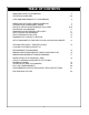
TABLE OF CONTENTS IMPORTANT SAFETY INFORMATION OPERATING GUIDELINES 4 5-6 CARE AND MAINTENANCE OF YOUR MINIMAX ADDITIONAL RECOVERY TANK INFORMATION PURGING NON-CONDENSABLE GASES HELPFUL HINTS FOR REFRIGERANT RECOVERY OPERATING YOUR MINIMAX DIAGRAM FOR REFRIGERANT RECOVERY SELF PURGING YOUR MINIMAX SELF PURGE/AUTO EVACUATE DIAGRAM FOR “PUSH/PULL” METHOD 6 7 8 9-10 11 11 12 12 13 SET-UP DIAGRAM FOR TANK PRE OR SUB COOLING PROCEDURE 13 OPTIONAL RECOVERY / TANK PRE OR SUB COOLING FOR FIXED HOSE SET-UP 14
m IMPORTANT SAFETY INFORMATION m 7.Read all safety information regarding the safe handling of refrigerant and refrigerant oil, including the Material Safety Data Sheet. MSDS sheets can be obtained from your refrigerant supplier. SAFETY COMES FIRST! Read all safety, operating guidelines and instructions before operating your Minimax. 1. CAUTION: ONLY A QUALIFIED TECHNICIAN SHOULD OPERATE THIS RECOVERY UNIT.
OPERATING GUIDELINES m Before operating the Minimax recovery unit, read the following m NEVER use a standarddisposable30lb.tank (the typeofcontainer in which virgin refrigerant is sold) to recover refrigerant. 1. MINIMAX IS APPROVED FOR USE WITH THE FOLLOWING CATEGORY III, IV and V REFRIGERANTS (Per ARI 740): 9. storage tank. DO NOT OVERFILL. Tank is full at 80% volume. Tank may explode if filled more than 80% duetoliquid expansion.
OPERATING GUIDELINES - cont. 15. To maximize recovery rates, use the shortest possible length of 3/8" or larger hose. A hose no longer than 3 feet is recommended. 16.For maximum throughput, always remove all unnecessary hose core depressors and the Schrader valves from port connections. 17.Deformed rubber seals and core depressors in hoses and faulty or unnecessary Schrader valves can restrict flow up to 90%. NOTE: If there is no liquid in the recovery tank, then the cooling method will not work.
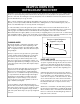
ADDITIONAL RECOVERY TANK INFORMATION m Warning: used for another refrigerant, completely empty the tank, evacuate it and purge the tank using dry nitrogen, and then re-evacuate it. Also read the information pertaining to recovery tanks, previously listed under Safety Information and Operating Guidelines. 3. Always store refrigerant containers in a cool dry place. 1. CAUTION: NEVER use a standard disposable 30lb. tank (the type of container in which virgin refrigerant is sold) to recover refrigerant.
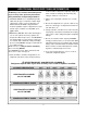
PURGING NON-CONDENSABLE GASES FROM REFRIGERANT TANK 5. If the pressure reading is higher than the pressure shown on the chart, very slowly (so as not to cause turbulence inside the tank) crack open the vapor port valve. Watch the pressure on the gauge decrease. To prevent venting, add 4-5 psi to the pressure shown on the chart. when the gauge corresponds to that pressure, close the vapor port valve. 1. Allow the tank to sit undisturbed for 24 hours. This allows the air to rise to the top. 2.
HELPFUL HINTS FOR REFRIGERANT RECOVERY Refrigerant recovery has come a long way in a few short years. On the surface it's simply the process of taking refrigerant out of a system and putting it into a tank. However, this simple process can quickly become problematic if a few items are overlooked. The following are some tips and pointers we've accumulated over the last few years that can save you time and make the process go smoother.
HELPFUL HINTS FOR REFRIGERANT RECOVERY - cont. This is probably never noticed in charging, because the pressure opens the grommet, but during recovery (or with suction) the deformed grommet severely restricts the flow of refrigerant. KEEPING THE DIRT OUT During the recovery process your recovery machine can be exposed to debris that can, potentially, damage it. This includes brazing spatter and copper/ brass slithers. Further contamination can be introduced from the refrigerant storage tanks.
OPERATING YOUR MINIMAX PROCEDURE FOR NORMAL SYSTEM RECOVERY necessary, under certain circumstances, to press this switch more than once to start the compressor. 1. Inspect the Minimax thoroughly to insure that it is in good operating condition. 2. Make sure all connections are correct and tight (see set-up diagram below). 8. Slowly open the input port on the Minimax. 4. Make sure the Recover/Purge valve is set on Recover. a.
SELF PURGING YOUR MINIMAX PROCEDURE FOR PURGING REMAINING REFRIGERANT FROM THE MINIMAX 1. Close the ports of the system being serviced that are connected to the input port of the Minimax. 7. Close the ports on the recovery tank and the Minimax. 2. Close the input port on the Minimax. 8. Turn the Minimax off. 3. Turn off the Minimax. 9. Return the Recover/Purge valve to the Recover position. 4. Turn the Recover/Purge valve to the Purge position. 10.Disconnect and store all hoses. 11.
DIAGRAM FOR “PUSH/PULL” METHOD Push/pull method only works with large systems where the liquid is readily accessible. Do not use this method on systems that contain less than 15 lbs. as it may not work. The sight glass is used to provide a method of determining the moisture content and quality of a system’s refrigerant. m CAUTION: When using the “Push/Pull” method, once the siphon is started, it can continue and overfill the storage tank even if the tank is equipped with a float level sensor.
OPTIONAL RECOVERY/TANK PRE OR SUB COOLING FOR FIXED HOSE SET-UP m A scale must be used to avoid over filling the storage tank. NORMAL RECOVERY: Tank Vapor valve is closed TANK PRE OR SUB COOLING: Tank Vapor valve is open and both manifold gauge set valves are closed.
REFRIGERANT FLOW DIAGRAM 15
MINIMAX PARTS DIAGRAM 29 26 27 1 25 13 14 15 16 23 17 28 18 2 3 12 19 30 4 20 21 5 24 7 22 6 8 9 11 10 MINIMAX PARTS LIST ITEM DESCRIPTION PART# 1 PLASTIC CASE (100118) 2 FAN GRILL, OUTLET (100179) 3 AXIAL FAN (100119) 4 CONDENSER (100139) 5 COMPRESSOR (CP1320) 6 COMPRESSOR BRACKET (100207) 7 COUPLER (CP1315) 8 BELL HOUSING (CP1001) 9 MOTOR BRACKET (100209) 10 MOTOR (EL1821) 11 12 13 14 15 16 17 18 19 20 21 FRONTPANEL MANIFOLD INPUT GAUGE OUTPUT GAUGE GAUGE LENS ON/OFF SWITCH STARTSWITC
MINIMAX WIRING DIAGRAM MINIMAX-KT WIRING DIAGRAM INCLUDING OPTIONAL TANK CAPACITY SENSING CIRCUITRY (KIT:KT5001) 17
INSTALLATION OF OPTIONAL 80% TANK CAPACITY SENSING COMPONENTS (KIT:KT5001) Note: PROMAX also offers the model, Minimax-KT, with the 80% Capacity Shut Off Kit installed at the factory. 10. Connect the white wire from the male side of the 3 pin connector (p/n EL1215) to terminal #1 of the relay. c Warning: Prior to performing any type of mainte- Note: Ensure that the green wire from the sensor cord is connected to the center of the 3-pin connector. (Note: only two wires are used in this connector).
TROUBLESHOOTING YOUR MINIMAX SAFETY FIRST Read and understand all safety information contained in this manual before servicing the unit.
FULL ONE YEAR WARRANTY MFG # Promax products are warranted to be free from defects in workmanship and materials for a period of one year from date of purchase. THE FOLLOWING RESTRICTIONS APPLY: 1. The warranty applies to products in normal use only, as described in the operating manual. The product must also be serviced and maintained as described therein. 2. If the product fails, it will be replaced at the option of Advanced Test Products, Inc. (ATP) 3.
THE UNITED STATES ENVIRONMENTAL PROTECTION AGENCY (EPA) REFRIGERANT RECOVERY AND RECYCLING DEVICE ACQUISITION CERTIFICATION FORM EPA regulations have required establishments that service or dispose of refrigerant or air conditioning equipment to certify that they have acquired recovery and recycling devices that meet the EPA standards for such devices since August 12. 1993.
INSTRUCTIONS EPA REGIONAL OFFICES Part 1. Please provide the name, address and telephone number of the establishment where the refrigerant recovery or recycling device(s) is (are) located. Please complete one form for each location. State the number of vehicles based at this location that are used to transport technicians and equipment to and from service sites. CONNECTICUT, MAINE, MASSACHUSETTS, NEW HAMPSHIRE, RHODE ISLAND, VERMONT CAA 608 Enforcement Contact: EPA Region 1.
ADVANCED TEST PRODUCTS. INC • Miramar, FL Telephone: (954) 499-5400 • Fax: (954) 499-5454 Toll Free: (800) 327-5060 www.PromaxRecovery.com Designed & Engineered in the USA Manufactured in China PN/ 100116 Rev.