
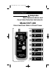
Instruction Manual
-4-
*
*
**
* *
**
* *
*
*
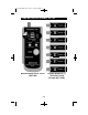
OPERATION INSTRUCTIONS
MAPPING FUNCTION
1. Map/Loc push button switch to the map (up) position.
2.
Set the straight/cross-pinning push button switch to either position.
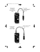
Communication Cable
3. Connect one end of the cable to be tested to the remote identifier and
the other end of any cable to the cable tracer.
4. Push the STEP button and read the result.
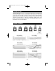
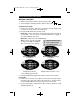
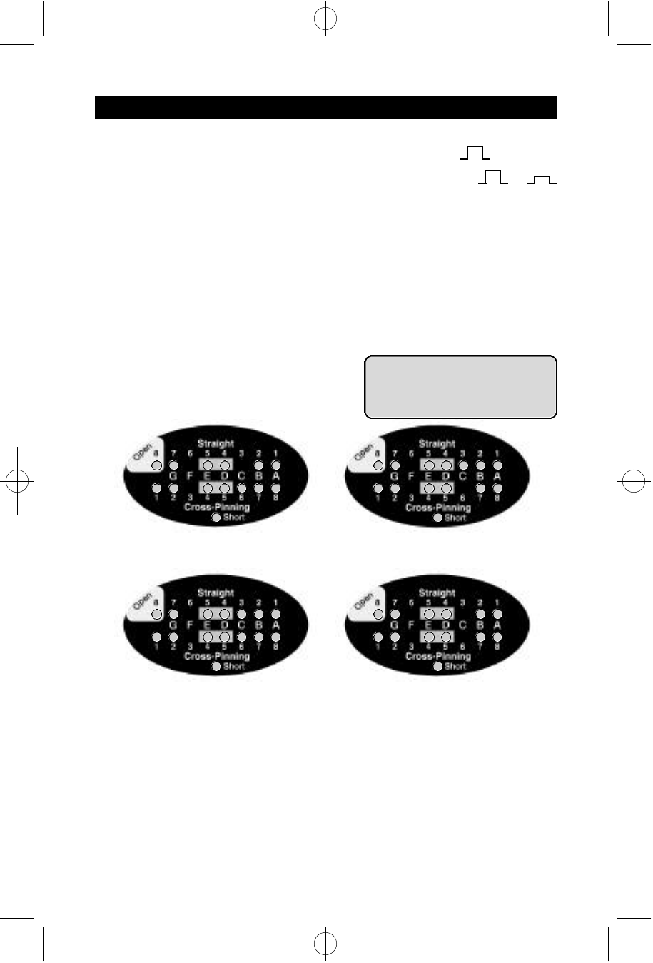
Good Pair: One bi-color (green and red) and one single color (green
or red) LEDs. The color of the second LED indicates a straight or
cross-pinned wiring for the pair.
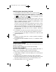
Open Pair: Only one bi-color LED blinking.
Short: Two or more bi-color LEDs
or single color LEDs are blinking
(two or more wires are shorted).
Good Pair (Straight)
3 & 6 Wires
Open Pair
Straight open wire #3
Cross-pinning open wire #6
Short
Straight cable short wires 1 & 2
Good Pair (Cross-Pinning)
3 & 6 Wires
5. Push the STEP button again and read the result for the next pair.
Coax Cable
6. Connect one end of the coax cable to be tested to the remote identi-
fier and the other end of the cable to the cable tracer. For this testing,
use the middle LEDs (boxed in as the gray color on the unit).
7. If you do not push the step button for 30 seconds, the cable tracer will
automatically shut off.
*
= Bi-Color Blinking LED
+
= Green Blinking LED
= Red Blinking LED
X
or
DCT-400 (CDD-1B) 2/12/01 3:55 PM Page 5