INSTRUCTION MANUAL ACD-14 TECH CLAMP AMPROBE ®
1 Congratulations! Your new instrument has been crafted according to quality standards and contains quality components and workmanship. It has been inspected for proper operation of all of its functions and tested by qualified factory technicians according to the long-established standards of AMPROBE. 1) SAFETY This manual contains information and warnings that must be followed for operating the instrument safely and maintaining the instrument in a safe operating condition.
2 WARNING: To reduce the risk of fire or electric shock, do not expose this product to rain or moisture. The meter is intended only for indoor use. To avoid electrical shock hazard, observe the proper safety precautions when working with voltages above 60 VDC or 30 VAC rms. These voltage levels pose a potential shock hazard to the user. Inspect test leads, connectors, and probes for damaged insulation or exposed metal before using the instrument. If any defects are found, replace them immediately.
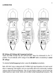
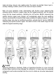
3) PRODUCT DESCRIPTION Note: Please refer to Specification Section for function details.
4) OPERATION 4 DC Voltage, AC Voltage, Hz Frequency functions Inputs are made through the test lead terminals. Move the slide-switch to the “V” position. The unit defaults at DC voltage. Press SELECT button momentarily to select AC voltage. To activate the Hz Frequency function, press the Hz button momentarily. Note: 400.
meter will show close to zero reading when the inputs are shorted. Open input is actually a floating condition, which is not a zero-volt-input condition. 5 Note: Hz input sensitivity varies automatically with function range selected while activating the Hz function. Lowest range has the highest sensitivity, and the highest range has the lowest sensitivity.
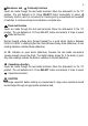
6 Ω Resistance, and Continuity functions Inputs are made through the test leads terminals. Move the slide-switch to the “Ω” position. The unit defaults at Ω. Press SELECT button momentarily to select Continuity function, which is convenient for checking wiring connections and operation of switches. A continuous beep tone indicates a complete wire. Diode test function Inputs are made through the test lead terminals. Move the slide-switch to the “Ω” position. The unit defaults at Ω.
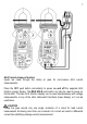
7 ACA Current clamp-on function Inputs are made through the clamp on jaws for non-invasive ACA current measurements. Press the OFF push button momentarily to power on and off the separate ACA function (upper) display. The MAX HOLD push button can also be used to power on this function. This twin ACA function display can be used simultaneously with voltage measurements or any of the other slide-switch functions (lower display) or it can be used alone.
Make sure the jaws are completely closed, or else it will introduce measurement errors. 8 Strong Electro-magnetic field environments such as high-current transformers, motors and conductors may affect measurement accuracy. Temperature function Insert the banana plug type-K temperature bead probe (TPK-59), observing the proper polarities. Move the slide-switch to the “°F/°C” position. The unit defaults at degree C (Celsius). Press SELECT button momentarily to select degree F (Fahrenheit).
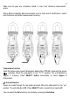
9 Application notes: 1) The DC µA function is designed especially for HVAC/R flame sensor applications. The 0.1µA resolution is useful for identifying the minute current changes in flame detector applications. Flame signal current check should indicate steady flame signal of at least 2µA for a rectification type, 1.5µA for an ultraviolet type, or 8µA for self-checking systems.
10 Auto-ranging When there is more than one measuring range under a selected meter function, the LED annunciator “a” turns on in the upper left corner. The meter will automatically switch to the best resolution range when making measurements. No manual ranging selection is required. Auto Power Off (APO) When the meter is on, the Auto Power Off (APO) feature will switch the meter into a sleep mode automatically to extend battery life after approximately 30 minutes of the last front panel activity.
11 Battery replacement The meter uses 2 standard 3V alkaline button batteries (ANSI/NEDA-5004LC, IEC-CR2030). The lower battery is used for the slide-switch functions, and the upper battery is used for the upper display ACA function separately. Low Battery Indication: When the battery voltage drops below approx. 2.4V, a battery symbol will appear in the upper right corner of the LCD display, indicating that the battery needs replacing.
12 6) Specifications General Specifications Display: 3-3/4 digits 4000 counts, dual LCD displays Update Rate: 3 per second nominal Polarity: Automatic Low Battery Indication: Below approx. 2.4V Operating Temperature: 32°F to 104°F (0°C to 40°C) Relative Humidity: Maximum relative humidity 80% for temperatures up to 88° F (31°C) decreasing linearly to 50% relative humidity at 104° F (40°C) Altitude: Operating below 6,562 ft (2000m) Storage Temperature: -4°F to 140°F (-20°C to 60°C), < 80% R.H.
13 E.M.C.
Ohms RANGE Accuracy 0.8% + 6d 400.0Ω 0.6% + 4d 4.000kΩ, 40.00kΩ, 400.0kΩ 1.0% + 4d 4.000MΩ 2.0% + 4d 40.00MΩ Open Circuit Voltage: 0.4VDC typical Capacitance RANGE* Accuracy** 500.0nF, 5.000µF, 3.5%*** + 6d 50.00µF, 500.0µF, 3000µF *Additional 50.00nF range accuracy is not specified **Accuracies with film capacitor or better ***Specified with battery voltage above 2.8V (approximately half full battery). Accuracy decreases gradually to 12% at low battery warning voltage of approximately 2.
LIMTED WARRANTY Your AMPROBE instrument has a limited warranty against defective materials and/or workmanship for one year from the date of purchase provided that, in the opinion of the factory, the instrument has not been tampered with or taken apart. Should your instrument fail due to defective materials, and/or workmanship during this 1-year period, a no charge repair or replacement will be made to the original purchaser.