Owner's Manual WS-165-132 Series Water Softener
Table of Contents 3 4 5 13 14
What is included with the WS-165-132 Check the entire unit for any shipping related damage, missing parts, or damage to shipping cartons. Contact the transportation company for all damage and loss claims. Tier1 is not responsible for damages in transit. Small parts, needed to assemble the Softener, are contained in parts bags A and B, the control valve box, or in the instruction(s) zip lock bag. To avoid loss of the small parts, keep them in the parts bag until you are ready to use them. 1.
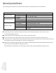
Operating Conditions This softening system will operate at maximum efficiency when the following conditions are considered: Operating Conditions: Working Conditions Working Environment Working pressure 21psi to 120psi Water temperature Environment temperature Relative humidity 40 °F - 120 °F (5°C - 50°C) Power source Inlet Water Quality 40 °F - 120 °F (5°C - 50°C) ( AC100~240V/50~60Hz ≤ 95% When temperature is 25°C/77°F Water turbidity Down-flow Regeneration < 5FTU Water hardness 1 grain per
ASSEMBLY INSTRUCTIONS Locate the following parts: 1. Brine Tank – inside the brine tank you will find: a. Bypass valve b. Control Valve c. Clear tubing d. Lubricant e. PVC tubing f. Upper distributor g. Brine valve h. Brine well i. Parts bag A i. Includes: 1. Brine well overflow elbow 2. Brine well mount k. Instruction manual(s) zip lock packet i. Includes 1. 165 Series owner’s manual 2.
ASSEMBLY INSTRUCTIONS 1. Resin Tank - the tank will have a temporary shipping cap, a master O-Ring, and a piece of tape covering the riser tube. The cap, master O-Ring (another is supplied) and the tape must be removed and discarded prior to attaching control valve and the upper distributor. This water softener includes regular control valve connections and a bypass valve connection; therefore, a set of installation components has been included for each method of installation.
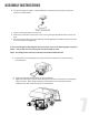
ASSEMBLY INSTRUCTIONS B. Connect the upper brine filter, or upper distributor, to bottom of control valve, line up slots and twist, as shown below C. Center the riser pipe within the resin tank D. Attach the control valve onto the resin tank, ensuring the upper distributor slides over the riser pipe E.
ASSEMBLY INSTRUCTIONS D. Insert water flow meter probe into on-board water meter probe dock, as shown below E. Proceed to step 4 Step 3: Assembly using the included by-pass valve A. Insert blue washers, from parts bag B, into input and output connections on the control valve, as shown below B. Remove the impeller from the outlet animated connector, located inside control valve box, as shown below C.
ASSEMBLY INSTRUCTIONS D. Attach the bypass valve onto the control valve, as shown below . E. Insert water meter probe from control valve into the by-pass valve’s on-board water meterprobe holder, ensure it is securely seated, as shown below Step 4: Connecting the line bine to the brine tank A.
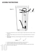
ASSEMBLY INSTRUCTIONS Figure 1.1 A. Attach brine well bracket (1) to brine tank by sliding brine well bracket over brine well, as shown in Figure 1.1 B. Secure brine well bracket (2) to top hole of brine tank using threaded attachment, as shown in Figure 1.1 C. Insert the PVC tube bushing, from parts bag B, into the end of the brine tube completely, as shown below 10 D. Feed PVC tubing (3) through the brine well bracket, as show in Figure 1.1 E.
ASSEMBLY INSTRUCTIONS G. Push the brine valve (5) all the way to the bottom of the brine well, ensuring not to loosen or kink PVC tubing, as shown in Figure 1.1 H. Insert the red brine line flow control, from parts bag B, with the cone side facing into control valve, in the control valve brine line connector, , as shown in the area of magnification below I. Tighten the nut onto the brine line connection, as shown in the area of magnification below STEP 5: Connecting overflow line to brine tank Figure 1.
ASSEMBLY INSTRUCTIONS C. Secure the clear drain tubing over a floor drain or other suitable drain. Check your local codes to ensure compliance. STEP 6: Connecting back wash hose to control valve A. Thread ribbed drain connector, from parts bag b, onto drain connection, as shown below D. Attach clear drain tube to connector, secure using a hose clamp, from the instruction manual(s) zip lock packet B. Secure the clear drain tubing over a floor drain, into a laundry tub, standpipe, or other suitable drain.
STARTUP INSTRUCTIONS ● • System Start-up Before operating for the first time, flush out the water line and bypass. Be sure the bypass is closed. • Turn the water source on at the inlet to the house. • Disconnect the bypass from the valve if attached to the valve. • Be sure to remove the meter impeller from the bypass before opening the bypass. • Put a container under the bypass and open the bypass to allow water to flow through and remove any foreign material out of the water lines. • Close the bypass.
MASTER PROGRAMMING * ● Programming Key Time of Day Indicator ∗ LED, displays the time of day. ∗ LED flashes, reset the time of day, see page 17, after electrical service has been interrupted for 3 days or more. Button Lock Indicator ∗ LED on, indicates the buttons are locked. ∗ To unlock, press and hold both and buttons simultaneously for 3 seconds until the LED turns off. Program Mode Indicator ∗ LED on, enter program display mode. Use or buttons to view all values. or buttons to adjust values.
MASTER PROGRAMMING ● ● Valve Programming Instructions When LED is on, press and hold both buttons simultaneously for 3 seconds to lift the button lock status. and To program the valve, press and the LED will turn on. This indicates you are in the programming mode. To navigate to each programming stage, press or . To adjust that programming stage value, press to adjust the values. Follow the process steps and use the or on the following page. To exit the programming, press and return to service status.
MASTER PROGRAMMING Function Indicator Factory Default Parameter Set Range Time of Day Random 00:00 ~23:59 A-01 A-02 Control Mode A-01 A-01 02:00 02:00 F-00 00 20L 20L 5 500L Yd1.2 1.2 0.1 9.9 Hardness Exchange Factor AL.65 Water Treatment Capacity Meter Immediate. Regeneration occurs immediately once the gallons used reaches zero (0). Meter Immediate - set resin volume, feed water hardness, and Regeneration Time Feed Water once the gallons used reaches zero (0).
MASTER PROGRAMMING ● Step by Step Programming Instructions Items Process steps Screen Display Note: when “12:12” flashes; Time of Day needs to be reset. 1. Press Time of Day Unit Mode to set Time of Day; both and will light and the “:” symbol will flash. 2. Press , both and “H" value will flash, press or to adjust hour value. 3. Press , both and “H” value will flash, press or to adjust minute value. 4. Press to accept adjustments made. Press 1. Press to enter Unit Mode, 2.
MASTER PROGRAMMING ● Step by Step Programming Instructions Continued 1. Press to enter Fast Rinse Time, Fast Rinse Time 2. Press or 3. Press to accept adjustments made. Press Maximum Regeneration Days 1. Press to enter Maximum Interval Regeneration Days, 2. Press or 3. Press to accept adjustments made. Press 1. Press to enter Signal Output Mode, 2. Press or 3. Press to accept adjustments made. Press Signal Output Mode and along with “5-10:00”value will flash.
WS-165-132 Series Water Softener Tier1® www.Tier1Filters.com Tier1® is a registered trademark of US Water Filters, Inc. Zumbrota, Minnesota Copyright © 2018 US Water Filters, Inc. All rights reserved.