Drum Brake Owners Manual
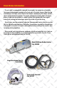
Drum Brake Information If your trailer is equipped with hydraulic drum brakes, the brakes are activated by the surge actuator/coupler located on the front end of the trailer tongue. When the tow vehicle stops, the trailer pushes into the tow vehicle, compressing the master cylinder that is located inside the actuator. The master cylinder forces brake fluid to the drum brakes.
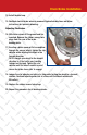
Drum Brake Installation 1. Using an adequate capacity floor or scissors jack, raise the side of the trailer. Block the wheels opposite the side being worked on both front and rear so that the trailer cannot roll. DO NOT rely on the jack as the only means of support. Always support the trailer with adequate capacity support stands. UNDER NO CIRCUMSTANCES IS THE TRAILER TO BE SUPPORTED BY THE TONGUE JACK WHILE BEING RAISED AT THE WHEELS! NOTE: Check under frames for brake lines BEFORE lifting.
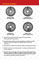
Drum Brake Installation Hydraulic Brake “Left” Drivers Side Hydraulic Brake “Right” Passengers Side Electric Brake “Left” Drivers Side Electric Brake “Right” Passengers Side 9. Mount the brake assembly to the brake flange with the mounting bolts. Mounting bolts should torque to 40 fps. 10. Inspect the original hub. Check the seal & bearings for wear. if there is any doubt whatsoever, go ahead and replace the seal and bearings and repack with fresh grease. 11. Reinstall the hub.
Drum Brake Installation 14. Install the dust cap. 15. Reattach electric brake wires or reconnect hydraulic brake lines and follow instructions for hydraulic bleeding.. Adjusting The Brakes 16. With trailer wheel off the ground and tire mounted. Remove the rubber access hole plugs from the rear of the brake backing plate. 17. Inserting a brake spoon or flat screwdriver through the access hole(s), tighten the star adjuster while rotating the wheel in the forward direction.
Bleeding the Brake System - Hydraulic Drum Bakes Only Use only DOT-3 heavy duty fluid in the actuator. Do not re-use brake fluid. Do not use any other type of brake fluid other than DOT-3. If pressure bleeding equipment is available, follow the manufacturer’s instructions in bleeding the system. These types of brake bleeders are available at your local automotive supply.
Electric Drum Brake Information Electric brakes are activated by a brake controller located in the tow vehicle. This is generally an accessory that must be purchased separately. Please research before buying. Some controllers work better with different brand tow vehicles. Electric drum brakes are not recommended for marine applications Electric brakes are individually adjusted in the same way the hydraulic drum brakes are adjusted that is covered in this manual.
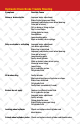
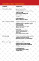
Hydraulic Drum Brake Trouble Shooting Symptoms Possible Cause Noise or brake chatter Improper brake adjustment. Brake fluid or grease on lining. Improperly adjusted or worn wheel bearing. Drum out of round. Dirt on drum or lining surface. Dust in rivet holes. Lining glazed or worn. Scored drum. Loose backing plate. Weak or broken return springs. Only one brake is activating Improper brake adjustment. (see brake adjustment) Brake line is restricted. Improperly adjusted or worn wheel bearing.
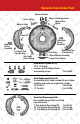
Return Spring Shoe Pin Upper Return Spring Adjuster Shim Hydraulic Drum Brake Parts Shoe Pin Return Spring Adjuster Shim Cylinder Assembly ft Brake Pad Return eeUpper Backing) Spring lugs Hold Down Spring Assembly Retainer Washer Rear Upper Return Spring Hold Down Spring Assembly Hold Down Spring Assembly Dust Plugs Wheel Ad Lower Ret Actuat Primary Pad Shoe Pin Right Brake Pad Dust Plugs (Free Backing) Wheel Adjuster Assembly Lower Return Spring Hold Down Spring Assembly Left Brake Pad (Fr
Electric Drum Brake Trouble Shooting Symptoms Possible Cause Noise or brake chatter Improper brake adjustment. Oil or grease on lining. Improperly adjusted or worn wheel bearing. Drum out of round. Dirt on drum or magnet surface. Dust in rivet holes. Lining glazed or worn. Scored drum. Loose backing plate. Weak or broken return springs. Only one brake is activating Improper brake adjustment. (see brake adjustment) Improperly adjusted or worn wheel bearing. Drum out of round. Loose backing plate.
Electric Drum Brake Parts Actuating Cam Return Spring Actuating Cam Return Spring Upper Return Upper Return Spring ctuating Level Spring Actuating Level Arm Arm Primary Pad wn HoldReturn Down Spring Spring ActuatingAssembly Level Arm Hold Down Spring Assembly embly Primary Pad U Sp Secondary Pad Dust Plugs Brake Adjuster Magnet & Spring Hold Down Spring Assembly Secondary Pad Dust Plugs gnet & pring Actuating Cam Brake Adjuster Lower Return Spring Lower Return Spring Hold Down Spring Assembl
TIE DOWN ENGINEERING 255 Villanova Drive SW, Atlanta, GA 30336 (404) 344-0000 • Fax (404) 349-0401 © 2011 TIE DOWN ENGINEERING, ALL RIGHTS RESERVED Instruction Manual #08095 0706011,C934 Drum Brake Owners Manual
Installation Instructions and Service Manual Model 66/660* Actuator for Trailer Brakes 6,600 lbs Capacity Drum Brake Ready or Disc Brake Ready US Patent No. 6,375,211 *Model 660 - Manufactured after March 2012 MODEL 66 ACTUATOR INSTALLATION INSTRUCTIONS IMPORTANT: READ AND UNDERSTAND THE ENTIRE INSTRUCTION/ASSEMBLY PROCEDURE BEFORE INSTALLING YOUR BRAKES AND ACTUATOR. The Model 66/660 works by the “surge” or “push” of the trailer toward the tow vehicle.
4. Check with your state motor vehicle department for laws concerning minimum trailer brake requirements. Some states may require brakes on all axles. 5. Road test trailer a short distance to activate the actuator several times. Check fluid level again. Remember, low brake fluid levels will result in hitch ball knocking. 6. When testing is completed, make sure master cylinder is filled to 3/8” below the top of the reservoir and filler cap is securely in place.
WARNING Actuator and brakes should always be flushed with fresh water after using trailer in corrosive conditions. This includes salt water, fertilizers and other corrosive materials. Before storing trailer remove brakes and clean thoroughly. It is also wise to repack the bearings at the same time. Failure to properly and adequately maintain the actuator could cause serious damage, injury or death.
9 Model 660* Disc Brake Parts Detail 4X 12 14 5 4X 15 *Model 660 - Manufactured after March 2012 6,600 lbs Capacity Disc Brake Ready W/Solenoid Installed 2 4 6X 13 10 11 2X 7 1B 18 2X 6 1A 2X 8 17 3 16 ITEM NO. QTY.
9 Model 660* Drum Brake Parts Detail 4X 11 6X 12 13 5 4X 14 *Model 660 - Manufactured after March 2012 6,600 lbs Capacity Drum Brake Ready 2 4 10 1B 2X 7 6 2X 8 2X 17 1A 15 3 16 ITEM NO. QTY.
TIE DOWN ENGINEERING LIMITED WARRANTY Limited Warranty TIE DOWN ENGINEERING Inc (“TIE DOWN”) warrants its products to be free from defects in material and workmanship for one year from date of delivery to the original purchaser when properly installed, used and maintained by the purchaser. This warranty does not apply to damage or loss caused by any or all of the following circumstances or conditions: • Damage caused during installation.
Instructions for Bleeding Tie Downs Model 660, 700 & 800 Actuators Place Screwdriver Tip Here 2A 1A Correct Front of Bracket Incorrect DO NOT USE SLOT 1B 2B Bleeding Access To pump master cylinder, insert a flat tip screwdriver into the round hole near the front of the actuator cover (See 1A). The screwdriver should be at the lowest angle possible to the actuator so that it slides in front of the e-stop bracket (See 1B).
Drill Hole Pattern for the Model 66/660, 70/700 & 80/800 Standard Housing Actuators June 18, 2012 Model 66/660 Actuators (2 bolts only) • Model 66/660 requires 2 - 1/2” x 4” Grade 5 bolts with lock washers (not included) • Model 70/700 & 80/800 Actuators requires 3 -1/2”x 4” Grade 5 bolts with lock washers (not included) • All TIE DOWN ENGINEERING standard actuators have the same hole pattern for consistent hole placement TIE DOWN ENGINEERING • 255 Villanova Drive SW • Atlanta, GA 30336 www.tiedown.
Single Axle Brake Line Kit (#80326) This brake line kit is designed to be used to replace existing brake lines or installed on a trailer that has not had brakes before. Read all of the instructions first and familiarize yourself with the parts and layout before starting the installation. Make sure your actuator is in good working condition, and that it is the proper model for your drum or disc brakes. 1.
Single Axle Brake Line Kit- Parts List #80326 24" Flex Hose (2) Union "T" (2) 76" Flex Hose 240" Flex Hose Union "T" Plug (1) Cable Ties (5) Cable Clamps (4) Self Taping Screws (8) "T" Clamp (2) Assembly Diagram Brake Plug Union "T" 24" Flex Hose Actuator 24" Flex Hose 76" Flex Hose Note: All Tie Down Brakes and Actuators use DOT3 brake fluid. Use of any other brake fluid may damage seals and voids the warranty. Brake TIE DOWN ENGINEERING • 5901 Wheaton Drive • Atlanta GA, 30336 www.