Eliminator Vented Disc Brake Owners Manual
Eliminator Vented Disc Brakes Exclusive Features “Whenever possible, the tendency is to use an aluminum alloy in order to reduce weight. These alloys are much lighter and are also much better heat conductors: 220W/m.˚K for aluminum compared to 44 W/m.˚K for cast iron”. That’s 5X faster! *Haynes Automotive Disc Brake Manual Bi-metal Piston Bi-metal piston combines a stainless steel outer jacket with an anodized aluminum inner sleeve to shed braking heat 5X faster than one piece stainless pistons.
Vented Rotor Disc Brakes, w/Aluminum Caliper Read your trailer manufacturer’s operating manual and follow the towing vehicle’s guidelines for towing capability, hitch requirements and other towing information. Congratulations on your decision to have Tie Down Engineering vented rotor disc brakes with aluminum caliper installed on your trailer. Disc brakes have many advantages over drum brakes.
Vented Rotor Disc Brakes, w/Aluminum Caliper Should you feel the tow vehicle and trailer brakes are not working as they should; have the tow vehicle and trailer inspected. Make sure your trailer’s GVW is within the tow vehicles capacity. If your trailer has multiple axles, verify that the GVW of the trailer does not exceed the capacity of the brakes, which is 3750 lbs on 10-inch (5 lug) brakes and 6000 lbs on 12-inch (6 lug) brakes, per axle. Some states require brakes on all axles.
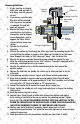
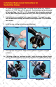
Removing Hub/Rotor Bleeder Valve 1. If your axle has an integral Vented style rotor, hub and rotor is Slider Pin Caliper one piece, and will come off as one. Brake Line Out 2. If you have a cap style rotor, Mounting the rotor will be removed Plate after the wheel and caliper is removed. The hub will come off separate. Spindle/Alxe 3. Elevate the trailer using the manufacturers instructions. Always use jack for support.
Installation/Replacement Instructions for Vented Disc Brakes 1. On a bare axle attach mounting plate to the brake flanges on the axle. Preferred position is at “12:00” high or to the back side. Exact positioning will be determined by the brake flange. Use 7/16” x 1-1/4” zinc hex bolts, lock nuts/washers and torque to 40 lbs. Note: brake mounting plates can have 2 or 4 holes for attaching to the axle. 2. If installation is on a completed trailer, remove tire/wheel.
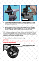
Step 5 Step 6 5. Place caliper over rotor and mounting plate. A bleeder valve must be in the up position (see below). Check both calipers for this position. Some calipers have two valves others have only one. 6. Apply a coating of Loctite® to threads on the mounting plate. Insert slider pins thru backside of rotor into mounting plate. Use a 7/16” hex socket and tighten both pins to 40 ft. lbs. Check for binding, make sure rotor spins freely. NOTE: Slider pins have a lock-thread coating.
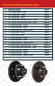
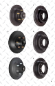
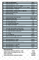
Parts List for Eliminator Vented Disc Brakes # 1 2 2 3 3 4 4 4 5 5 6 6 6 7 7 8 8 8 1 7 Eliminator Rotors 8.15” Vented Rotor - E-coat 9.6” Vented Rotor - E-coat 9.6” Vented Rotor - GalvX 9.6” Vented Turbo Lube/Vortex Rotor - E-coat 9.
3 4 6 6 7 8 8
# 1 2 3 4 5 6 7 8 9 9 10 11 11 11 12 13 14 15 16 17 Brake Part Descriptions Part # Caliper Assembly (8.15” rotor) 46901A Caliper Assembly (9.6”, 10” & 12” rotors) 46304S Caliper Assembly - Stainless Steel (9.
1 2 3 4 5 6 7 8 9 10 10A 11 10B 10C 11A 11B 12 11C 14 15 13 16 17
TIE DOWN ENGINEERING 255 Villanova Drive SW, Atlanta, GA 30336 (404) 344-0000 • Fax (404) 349-0401 © 2011 TIE DOWN ENGINEERING, ALL RIGHTS RESERVED Instruction Manual #08075 050511,C1184 Eliminator Vented Disc Brake Owners Manual
Installation Instructions and Service Manual Model 66/660* Actuator for Trailer Brakes 6,600 lbs Capacity Drum Brake Ready or Disc Brake Ready US Patent No. 6,375,211 *Model 660 - Manufactured after March 2012 MODEL 66 ACTUATOR INSTALLATION INSTRUCTIONS IMPORTANT: READ AND UNDERSTAND THE ENTIRE INSTRUCTION/ASSEMBLY PROCEDURE BEFORE INSTALLING YOUR BRAKES AND ACTUATOR. The Model 66/660 works by the “surge” or “push” of the trailer toward the tow vehicle.
4. Check with your state motor vehicle department for laws concerning minimum trailer brake requirements. Some states may require brakes on all axles. 5. Road test trailer a short distance to activate the actuator several times. Check fluid level again. Remember, low brake fluid levels will result in hitch ball knocking. 6. When testing is completed, make sure master cylinder is filled to 3/8” below the top of the reservoir and filler cap is securely in place.
WARNING Actuator and brakes should always be flushed with fresh water after using trailer in corrosive conditions. This includes salt water, fertilizers and other corrosive materials. Before storing trailer remove brakes and clean thoroughly. It is also wise to repack the bearings at the same time. Failure to properly and adequately maintain the actuator could cause serious damage, injury or death.
9 Model 660* Disc Brake Parts Detail 4X 12 14 5 4X 15 *Model 660 - Manufactured after March 2012 6,600 lbs Capacity Disc Brake Ready W/Solenoid Installed 2 4 6X 13 10 11 2X 7 1B 18 2X 6 1A 2X 8 17 3 16 ITEM NO. QTY.
9 Model 660* Drum Brake Parts Detail 4X 11 6X 12 13 5 4X 14 *Model 660 - Manufactured after March 2012 6,600 lbs Capacity Drum Brake Ready 2 4 10 1B 2X 7 6 2X 8 2X 17 1A 15 3 16 ITEM NO. QTY.
TIE DOWN ENGINEERING LIMITED WARRANTY Limited Warranty TIE DOWN ENGINEERING Inc (“TIE DOWN”) warrants its products to be free from defects in material and workmanship for one year from date of delivery to the original purchaser when properly installed, used and maintained by the purchaser. This warranty does not apply to damage or loss caused by any or all of the following circumstances or conditions: • Damage caused during installation.
Instructions for Bleeding Tie Downs Model 660, 700 & 800 Actuators Place Screwdriver Tip Here 2A 1A Correct Front of Bracket Incorrect DO NOT USE SLOT 1B 2B Bleeding Access To pump master cylinder, insert a flat tip screwdriver into the round hole near the front of the actuator cover (See 1A). The screwdriver should be at the lowest angle possible to the actuator so that it slides in front of the e-stop bracket (See 1B).
Drill Hole Pattern for the Model 66/660, 70/700 & 80/800 Standard Housing Actuators June 18, 2012 Model 66/660 Actuators (2 bolts only) • Model 66/660 requires 2 - 1/2” x 4” Grade 5 bolts with lock washers (not included) • Model 70/700 & 80/800 Actuators requires 3 -1/2”x 4” Grade 5 bolts with lock washers (not included) • All TIE DOWN ENGINEERING standard actuators have the same hole pattern for consistent hole placement TIE DOWN ENGINEERING • 255 Villanova Drive SW • Atlanta, GA 30336 www.tiedown.
Single Axle Brake Line Kit (#80326) This brake line kit is designed to be used to replace existing brake lines or installed on a trailer that has not had brakes before. Read all of the instructions first and familiarize yourself with the parts and layout before starting the installation. Make sure your actuator is in good working condition, and that it is the proper model for your drum or disc brakes. 1.
Single Axle Brake Line Kit- Parts List #80326 24" Flex Hose (2) Union "T" (2) 76" Flex Hose 240" Flex Hose Union "T" Plug (1) Cable Ties (5) Cable Clamps (4) Self Taping Screws (8) "T" Clamp (2) Assembly Diagram Brake Plug Union "T" 24" Flex Hose Actuator 24" Flex Hose 76" Flex Hose Note: All Tie Down Brakes and Actuators use DOT3 brake fluid. Use of any other brake fluid may damage seals and voids the warranty. Brake TIE DOWN ENGINEERING • 5901 Wheaton Drive • Atlanta GA, 30336 www.