
User Manual
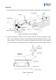

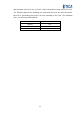
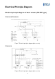
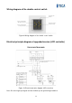

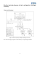
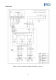
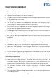
Table Of Contents
- Product Overview
- Features
- Use Conditions
- Precautions/Safety
- Appearance Overview
- Specifications
- Controller
- Basic model - double control switch
- 1) Power-on/off
- 2) Fan speed regulation
- Upgraded version - LCD controller
- 1) Power-on/off
- 2) Fan speed regulation
- 3) Work duration threshold setting for the filter
- 4) Filter reset
- High configuration version - Intelligent controller
- 1) Power-on/off
- 2) Fan speed regulation
- 3) Operating mode switching
- 4) Auto mode
- 5) Filter reset
- 6) Timed on/off and time adjustment
- Installation
- Electrical Principle Diagram
- Electrical Installation
- Operation and Maintenance
- After-sales Service

16
Electrical principle diagram of high configuration (intelligent
controller)
TRV015ACC/TRV025ACC
Controller
Live wire
Neutral line
Neutral line
High speed
Medium
speed
Low speed
★ Note: Short-circuit the high-speed
level and the medium-speed level.
Neutral line
High speed
Low speed
Power supply: 220 V ~ 50 Hz
Blue
Blue
Black Black
Brown
Brown
Yellow/green
Yellow/green
Blue
Black
★ Note: The dashed lines indicate
the wires to be connected on site.
Symbol
Name
Terminal block
Starting capacitor
Speed regulating capacitor
Fresh air fan
Discharge fan
Circuit breaker
Intelligent LCD controller
Figure 12 Electrical principle diagram (intelligent controller)
Note: Short the high speed gear and the medium speed gear during installation.