
User Manual

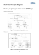
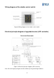

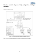
Table Of Contents
- Product Overview
- Features
- Use Conditions
- Precautions/Safety
- Appearance Overview
- Specifications
- Controller
- Basic model - double control switch
- 1) Power-on/off
- 2) Fan speed regulation
- Upgraded version - LCD controller
- 1) Power-on/off
- 2) Fan speed regulation
- 3) Work duration threshold setting for the filter
- 4) Filter reset
- High configuration version - Intelligent controller
- 1) Power-on/off
- 2) Fan speed regulation
- 3) Operating mode switching
- 4) Auto mode
- 5) Filter reset
- 6) Timed on/off and time adjustment
- Installation
- Electrical Principle Diagram
- Electrical Installation
- Operation and Maintenance
- After-sales Service

13
Electrical Principle Diagram
Electrical principle diagram of basic version (ON/OFF type)
TRV015ACA/TRV025ACA
★ Note: The dashed lines indicate the wires to be connected on site.
Low speed
High speed
Blue
Blue
Black Black
Power supply 220V ~ 50Hz
Blue Blac k
Brown
Brown
Yellow/green
Yellow/green
Symbol
Name
Terminal block
Starting capacitor
Speed regulating
capacitor
Fresh air fan
Discharge fan
Circuit breaker
Double-speed switch
Figure 7 Electrical principle diagram (basic version)
TRV035ACA
High speed
Low speed
Power supply 220V ~ 50Hz
Orange
Black Red
Blue
Orange
Blac k Red
Blue
Yellow/green
White
Yellow
White
Yellow
Yellow/green
★ Not e: The dashed lines indicate the
wires to be connected on site.
Blue
Red
Blac k
Orange
Symbol
Nam e
Terminal block
Starting capacitor
Fresh air fan
Discharge fan
Circuit breaker
Double-speed switch
Figure 8 Electrical principle diagram (basic version)