
User Manual
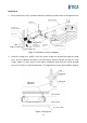

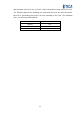
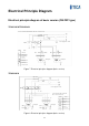
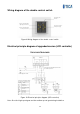

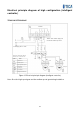
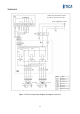
Table Of Contents
- Product Overview
- Features
- Use Conditions
- Precautions/Safety
- Appearance Overview
- Specifications
- Controller
- Basic model - double control switch
- 1) Power-on/off
- 2) Fan speed regulation
- Upgraded version - LCD controller
- 1) Power-on/off
- 2) Fan speed regulation
- 3) Work duration threshold setting for the filter
- 4) Filter reset
- High configuration version - Intelligent controller
- 1) Power-on/off
- 2) Fan speed regulation
- 3) Operating mode switching
- 4) Auto mode
- 5) Filter reset
- 6) Timed on/off and time adjustment
- Installation
- Electrical Principle Diagram
- Electrical Installation
- Operation and Maintenance
- After-sales Service

10
Installation
1. Follow instructions in this operation manual to install the product. Refer to the figure below.
Return air pipeline
Lifting bolt
Fresh air pipe
insulation material
Pipe cover
OA
(outdoor fresh air)
EA
(discharge air)
Thermal insulation
material for
discharge duct
Air supply
grille
Return air grille
SA
(supply air)
RA
(return air)
Figure 3 Installation reference diagram
2. Install the fixing bolts (M10), route the metal suspension bracket through the fixing
bolts, and use gaskets and nuts to fix the bracket. Ensure that the unit has no foam
scraps, paper, or other objects inside before installation and check the inside through
access holes before connecting the ducts. The figure below shows the installation method.
Lifting bolt
(Φ8~Φ10)
Nut
Flat gasket
Lifting part
Roof
Above 20mm
Above 25mm
Decorate ceiling
Figure 4 Lifting bolts