www.tica.
Contents Safety Precautions .............................................................................................................. 5 Installation of ODU .............................................................................................................. 6 Dimension ....................................................................................................................................... 8 Installation space .......................................................................
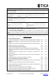
Application Form for Debugging Inverter VRF Air Conditioning Unit (Filled by Installer) Full name of the installer:___________________________________________________________ Address of the installer:____________________________________________________________ Owner's name or employer:_________________________________________________________ Person to contact:_______________________________Tel:______________________________ Installation site:_________ Province _________ City ________________________________
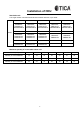
Application Form for Debugging Inverter VRF Air Conditioning Unit (Filled by Installer) 4. Check air duct system before installation a. Whether the installation of air duct system is designed by professionals Yes ( ) No ( ) b. Whether external residual pressure matched actual resistance of air duct Yes ( ) No ( ) c. Whether air duct system is provided with static pressure box for air supply and return Yes ( ) No ( ) d.
Safety Precautions Caution: Read this manual carefully before installation and use of the unit. The following standard is applied to this product This installation manual is applied to TICA TIMS-S/ST/SA/SRYA series R410A refrigerant inverter VRF air (cooling only) conditioning units. The manual is subject to change based on improvement on air conditioners without further notice. Preparation before installation ● Installation shall be left to a licensed professional.
Installation of ODU Standard mode The single outdoor unit starts from 8HP and increases with 2HP, up to 34HP Model 8HP 10HP 12HP 14HP 16HP TIMS080-S TIMS080-ST TIMS252CSRYA TIMS100-S TIMS100-ST TIMS285CSRYA TIMS120-S TIMS120-ST TIMS335CSRYA TIMS140-S TIMS140-ST TIMS400CSRYA TIMS160-S TIMS160-ST TIMS450CSRYA 18HP 20HP 22HP 24HP 26HP TIMS180-S TIMS180-SA TIMS180-ST TIMS200-S TIMS200-SA TIMS200-ST TIMS220-S TIMS220-SA TIMS200-ST TIMS240-S TIMS240-SA TIMS260-S TIMS260-SA 28HP 30HP 32HP
Installation of ODU Dimension Model:TIMS080-S/ST TIMS252CSRYA Model:TIMS140-S/ST TIMS400CSRYA TIMS100- S/ST TIMS120- S/ST TIMS285CSRYA TIMS160-S/ST TIMS335CSRYA TIMS180-ST TIMS450CSRYA 7
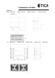
Installation of ODU Dimension Model:TIMS180-S TIMS200- S/SA/ST TIMS220- S/SA/ST TIMS240- S/SA/ST TIMS260-S 机型:TIMS260- SA TIMS280- S/SA TIMS300- S/SA 8 TIMS320- S/SA TIMS340-SA
Installation of ODU Installation space Requirements for installation position ● The installation position shall have sufficient strength to bear the unit weight and its vibration during operation. If the ODU is installed on a roof, make sure the roof is strong enough and water-proof. ● The ODU shall be installed in a well ventilated place to ensure good heat exchange. ● Places unsuitable for installation: ▲ The place where acid or alkaline substance or corrosive gas(e.g.
Installation of ODU Wall heigh t: not limi ted Dive rsi on d evice Front Installation space of a unit: 1. Installation space of a unit A unit should be installed in space surrounded by walls. The walls at its both sides is unlimited in height.
Installation of ODU 2. Unit installation in a single row The unit should be installed in space surrounded by walls Rear Rear Rear Front Front Front The front and one side of the ODU are in open areas 3.
Installation of ODU The front and one side of the ODU are in open areas 3.
Installation of ODU Handling Notes: ● Fragile and handle with care. ● The degree of inclination shall not exceed 30° while handling (do not put the unit on its side). ● Keep heat exchange fins safe while handling and installing the unit. In case of any damages, please use fin comb to fix it up. ● Properly dispose of packaging bags and prevent kids from playing with them.
Installation of ODU ODU Base Gro und screw fixin g h ole 4-ø 15 Sizes o f A and B in the abo ve figure are shown in the table below: Model TIMS080-S ~ TIMS120-S TIMS080-ST ~ TIMS120-ST TIMS252、280、335CSRYA TIMS140-S ~ TIMS160-S TIMS140-ST ~ TIMS180-ST TIMS400、450CSRYA TIMS180-S ~ TIMS260-S TIMS180-ST ~ TIMS240-ST TIMS200-SA ~ TIMS240-SA TIMS280-S ~ TIMS340-S TIMS260-SA ~ TIMS340-SA 14 A B 728mm 930mm 1038mm 1240mm 1375mm 1500mm 1745mm 1900mm
Installation of Refrigerant Piping ● Concrete foundation: the foundation shall be above the ground for at least 150 mm. 150 mm 100 mm Shock-absorbing pad ● Use anchor bolts, nuts and pads to fasten the ODU tightly to the base. Caution: shock-absorbing pads need to cover the entire bottom of the unit, and the pad thickness is greater than or equal to 20 mm. ● For anti-corrosive models: use rubber pads. If the nut joints get loose, the unit will not be corrosion proof.
Installation of Refrigerant Piping Precautions for the installation of piping: ● Use clean piping that is free from dust, moisture or any other substances. ● Store all the pipelines needed for installation indoors, and keep two ends of pipelines sealed till welding. ● Pass copper pipes into the holes at wall and seal the holes to prevent dirt coming in. ● Do not do ODU piping work on rainy days, lest that moisture and dirt would enter the pipelines.
Installation of Refrigerant Piping Definition H1*1 Limit (actual length) Remarks When the ODU is at the upper position: < 50 m Level difference between the IDU and ODU When the ODU is at the lower position: < 40 m H2*1 Level difference among IDUs < 20 m L1*2 The distance from the farthest IDU to the first branch pipe of the IDU. < 40 m LM The distance between the ODU and indoor first branch pipe < 90 m L1-L2 T The distance from the farthest IDU to the first branch pipe of the IDU.
Determination of diameter of branch pipe of the IDU The IDU is equipped with branch pipes h~p. Refer to the following table for the selection of the branch pipe size.
Installation of Refrigerant Piping Remarks: The equivalent longest piping distance from the IDU to components of the first branch pipe shall be no more than 40 m. However, when all the following conditions are met, it is allowed to extend the length to 90 m. (in the case of "using TICA branch pipe".) Required conditions Legends 1.
Installation of Refrigerant Piping Direct selection of refrigerant piping The copper pipe for main pipelines (LM) shall have the sizes chosen from the following table based on the total capacity of ODUs at the upper reaches (the ones unlabeled can be generally applied) ODU capacity (HP) Piping length (LM + L1) < 90 m Main pipe length (LM) < 40 m Piping length (LM + L1) < 90 m Piping length (LM + L1)> 90 m Main pipe length (LM) > 40 m Liquid pipe (mm) Gas pipe (mm) Liquid pipe (mm) Gas pipe (mm) Liqui
Installation of Refrigerant Piping ● The piping between the last-level branch pipe and IDU should have the same size with the IDU connecting pipe. ● The pipe between branch pipes should be based on the total capacity of downstream IDUs connected to the pipe. Total capacity of connected IDUs (kw) Liquid Pipe Gas Pipe Specifications (mm) Specifications (mm) X<16.8 Φ 9.52 Φ15.88 16.8 ≤ X < 22.5 Φ9.52 Φ19.05 22.5 ≤ X < 33.0 Φ9.52 Φ22.23 33.0 ≤ X < 46.0 Φ12.7 Φ25.40 46.0 ≤ X < 67.0 Φ15.88 Φ28.
Installation of Refrigerant Piping Branch pipes can be vertically or horizontally installed and as close as possible to the IDU. When installed horizontally, the angle shall be between ±15°.
Installation of Refrigerant Piping TBP4033TA TBP4072TA 23
Installation of Refrigerant piping TBP4073TA Qty: 2 Qty: 2 24
Installation of Refrigerant Piping Refrigerant piping length Capacity combination ΣRated cooling capacity of IDU Rated cooling capacity of ODU 50% ≤ ≤ 130% Remarks: It is recommended that the above value shall not be greater than 100% when selecting models. For scenarios with lower simultaneous usage coefficient, the above value may exceed 100%.
Air Tightness Test, Vacuuming and Supplementing Refrigerant For TIMS units, vacuum pump, pressure gauge, compound pressure gauge and charging hose used for R410A refrigerant are different from those used for R22 refrigerant. Make sure to use R410A dedicated tools. Air tightness test Steps: (1) Use a vacuum pump to discharge air out of the system from the spool of liquid-side check valve. Hold gauge pressure at -1 kgf/cm2 for one hour.
● vacuumizing, verify that gas and liquid side check valves of ODU are closed. Use tools dedicated to R410A, such as pressure gauges and filling pipes.
Air Tightness Test, Vacuuming and Supplementing Refrigerant Supplementing refrigerant Principles: Before delivery, the ODUs have been charged with a certain amount of refrigerant, but which cannot meet the needs of extended pipes. So refrigerant has to be added according to the actual length of refrigerant piping at installation site. Steps: ● Close compound pressure gauge, replace vacuum pump with charge tank connected with charging pipe.
Electric Control Installation Wiring cautions Cautions for power wiring ● Use copper wire as power wire and do not make it too tight. ● The IDU and ODU use different circuits: the ODU uses a three-phase power supply, while the IDU uses a single-phase power supply ● All the IDUs and ODUs of the same system must be supplied with power simultaneously. ● The distribution box shall be provided with a set of electric leakage protection device and air switch for each module.
Electric Control Installation Wiring specifications Notes: ● As wires need to be bent during installation process, it is recommended to use flexible wires, otherwise installation may fail. ● The parameters in the table below are corresponding to multiple strands of flexible copper wires. If other wires are selected, please refer to electrician's manual based on wiring current provided in the table.
TIMS260-S 418/342 TIMS260-SA ODU model Power supply TIMS280-S TIMS300-S 418/342 TIMS300-SA 80 418/342 TIMS340-SA 35mm2 20-50 35mm2 Length (m) GND 25mm2 ≤20 25mm2 35mm2 20~50 35mm2 25mm2 ≤20 25mm2 35mm2 20-50 25mm2 ≤20 35mm2 20-50 35mm2 25mm2 ≤20 25mm2 418/342 35mm2 20-50 35mm2 Communication line 80 /50Hz TIMS320-SA 25mm2 80 3N/380V TIMS320-S ≤20 Voltage Wiring General range (V) current (A) power cord 418/342 TIMS280-SA 25mm2 80 35mm2 0.75-1.
To centralized controller (Optional) Control main board of master unit The shield layer must be grounded! Communication cables must be laid out and connected in series in the bus structure; otherwise, faults may occur.
ODU Control Panel Main board in old version Digital display Code settings Notes: a. "0" for the status above, and"1" when dialed to the "ON" position. b. Description of ODU address setting: based on the specific situation after installation is completed. c. The unit must be powered on again after the DIP switch is reset.. d. The ODU capacity code has been set properly before delivery. Please check whether the setting is correct.
ODU Control Panel DIP switch: S1 is 2-bit, S2 is 4-bit, and S3 is 4-bit ● S1: ODU capacity code (reserved), on need to dial at present ● S2: System configuration DIP switch No. Function Dialed to “0” Dialed to “1” S2-1 Master unit/slave unit Slave unit Master unit Remarks: When there are not any modules in series, DIP switch must be “1”.
Main board in new version DIP switch: S1 is 8-bit, S2 is 6-bit, and S3 is 6-bit ● ● ● S1: DIP series switch Meaning/DIP switch S1-5 S1-6 S1-7 S1-8 CST 0 0 0 0 CXT 0 0 0 1 CSA 0 0 1 0 CXA 0 0 1 1 CXC 0 1 0 0 CSRYA 0 1 0 1 CXRYA 0 1 1 0 CSC 0 1 1 1 DSA 1 0 0 0 DXA 1 0 0 1 S2: system configuration DIP switch, unit defaulted to master unit; factory default Meaning/DIP switch S2-1 S2-2 S2-3 S2-4 Master unit 1 0 0 0 S3: DIP switch of ODU capacit
ODU Control Panel Settings of relevant keys 1.
ODU Control Panel Settings of relevant keys: Contents 3. Description of specific operations Press KEY2/3 (Chang e the correspond ing para me ter value) Press KEY1 Corresponding parameter value Parameter number Digital display: dP04 SP03 SP04 Address setting Digital display: Ar01-99 Baud rate Digital display: b-12…b-96, b192 Press KEY4 (Each tim e you press t he key, the parameter n umber SP** SP05 Model setting Digital display: C5-0\1\2 increases b y 1.
ODU Control Panel Digital display ● Description of contents showed on the digital display When operation mode varies, N digital display will show the new mode correspondingly; normally it will display this mode for 5s before displaying real-time clock; in the case of malfunctions, it will display the current malfunction code.
ODU Control Panel Code Content Handling by the Machine E015 Tho8 fault of 2# compressor discharge temperature sensor 2# compressor stop E016 1# compressor top temperature sensor FCo1 fault 1 # compressor stop E017 2# compressor top temperature sensor FCo2 fault 2# compressor stop E018 Reserved / E019 Reserved / E020 Abnormal capacity distribution between IDU and ODU ODU stops E021 Low pressure sensor fault ODU stops E022 High pressure sensor fault ODU stops E023 phase loss or rev
Trial Operation Before trial operation Make sure to check: ● ● ● ● Installation Whether the air conditioning unit can be securely fixed at the site. Whether the place is well ventilated and large enough for maintenance. Whether the number of IDUs connected to ODU is allowable. Wiring Whether the insulation for the loop of main power supply is intact. Check insulation status against national regulations. Whether power cord and communication cable have allowable length.
Trial Operation Trial operation check Start cooling or heating operation using a wired controller or remote controller. ● After 5 minutes, check whether there is cold (hot) air from IDU. ● Check all the IDUs in the same way. ● If any wiring or piping errors are found, please correct the errors and start trail operation again. Notes: ● Start another IDU one minute before the current IDU stops, which could save trial operation time.
Description of Hazardous Substances Environmental protection description This product complies with the environmental protection requirements of the Measures for the Administration of the Restricted Use of the Hazardous Substances Contained in Electrical and Electronic Products. Environmental protection service life: In the environmental protection service life, the user's normal use of this product will not cause serious pollution to the environment or cause serious damages to persons and properties.
Follow the Official Site of TICA PRO LLC www.tica.ru «TICA PRO» LLC Tel.: +7 495 127 79 00, +7 969 190 85 85 E-mail: info@tica.pro www.tica.