
Data Sheet

2 IO Ninja Hardware Manual (NHM)
©2000-2018 Tibbo Technology Inc.
Has three operating modes: RS232, RS485
[Note 2]
, and UART (TTL
[Note 3]
),
selectable via a slide switch.
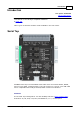
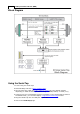
All inputs are connected to an 18-position, quick-release terminal block.
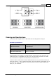
o RS232 mode:
Two onboard DB9 connectors — male and female — offer true "cable wedge"
sniffing
[Note 4]
;
Six jumpers for swapping and loopbacking signals within RX/TX, RTS/CTS, and
DTR/DSR pairs
[Note 5]
;
Six bi-color LEDs indicate the status of monitored lines and allow distinguishing
between the positive voltage (red), negative voltage (green), and zero
voltage (off) states
[Note 5]
;
DB9 connectors additionally pass through DCD and RI signals (without
monitoring them).
o RS485 mode:
Only TX and RX line pairs are monitored.
o TTL UART mode:
Can monitor UARTs of IC chips using logic levels from 5V down to 1.8V.
Full-speed (12Mhz) USB2.0 interface on a USB-C connector.
Six yellow LEDs indicate the state of six monitored lines as they enter the USB
controller. LEDs turn on when the lines go LOW
[Note 6]
.
USB-powered, no additional external power necessary.
Compact, outside dimensions only 82 x 74 x 30 mm.
Supplied with a USB-C cable and two DB9 gender changers.
Note 1
A more accurate version of this statement would be: "Monitors two TX, two RTS,
and two DTR lines," but that would be somewhat confusing to the reader. For
clarity, we chose to list the lines as they are commonly known: TX, RX, RTS, CTS,
DTR, and DSR. Keep in mind, however, that when it comes to sniffers, these names
are relative and depend on the view. For two interconnected serial devices, a TX
line on one end is an RX line on the other end. If so, which line is a "TX" and which
line is an "RX" from the sniffer's point of view? Only you can answer this question.
The Serial Tap itself has two inputs capable of monitoring serial data lines. Although
they are both identical inputs, one is marked "TX" and another one is marked "RX."
The same goes for other signals — RTS, CTS, DTR, and DSR. All these lines are
inputs of the Tap. We gave them "regular" names to make the use of the Serial Tap
intuitively easier. The same goes for RS485 lines. RX+/- and TX+/- pairs are both
inputs of the Serial Tap.
This said, the Serial Tap incorporates two DB9 connectors, for which the distinction
between TX and RX lines, RTS and CTS lines, and DTR and DSR lines is real. To give
our terminology an anchored point of view, we have decided that the DB9-M
connector on the left of the Tap is our "primary side" RS232 connector. For the
entire board, all signal names are consistent with the standard pin assignment of
this primary DB9-M connector. Of course, all "anchoring" disappears as soon as you
abandon DB9s and plug into the terminal block lines.
Note 2
These inputs can also be used for monitoring RS422 communications.